HA-W400RF (EG)/(EK)
(No.70245) 17
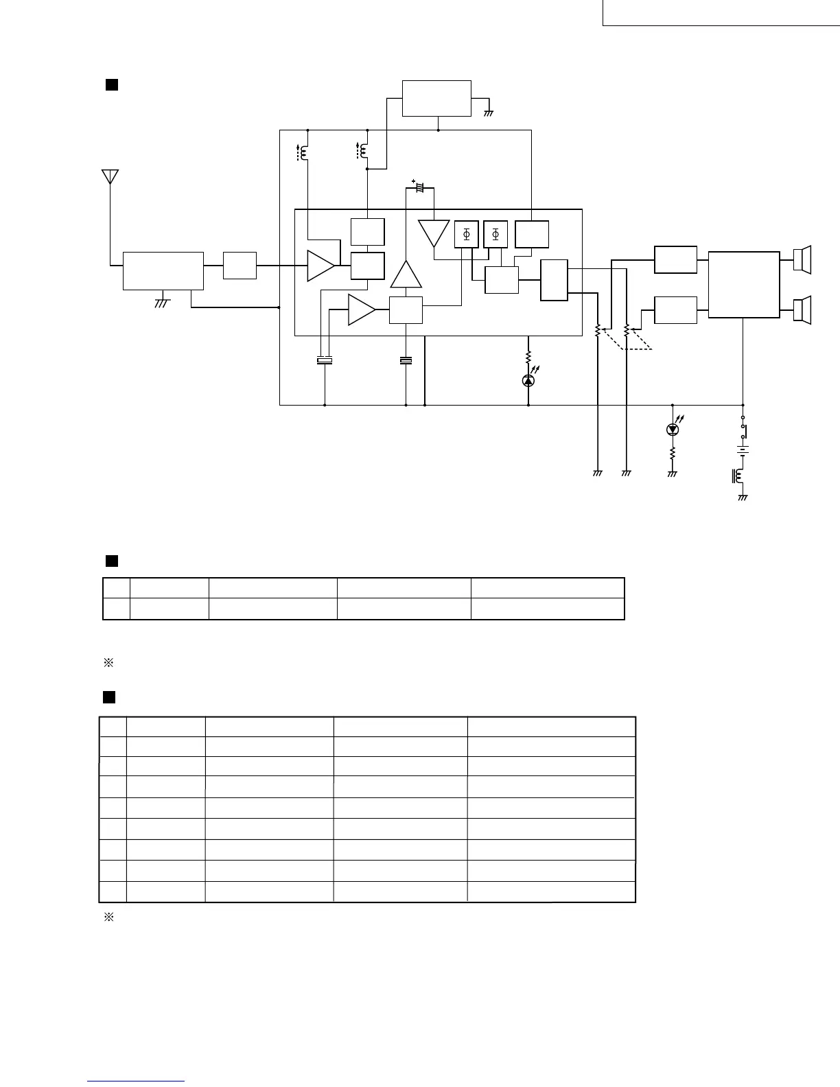
8.Block Diagram
9.Electric Parts List
Receiver (Headphones)
Transmitter
Receiver (Headphones)
IC1:TA2111F
AT
FILTER
UHF
MODULE
FM
FM
FM
MIX
OSC
23
48 12 6 11
21 19 17 15
1
F.F
14
13
DEC
VCO
FILTER
FILTER
VOL.CONTROL
HEADPHONE
AMP
IC2:TDA2822S
1
7
6
2
3
Rch
Lch
Ni-Cd Battery
(1.2V) x 2
POWER
INDICATOR
(Red)
INDICATOR
(Green)
STEREO
RF
AMP
FM
FM
AF
IF
DET
PRE
AMP
! No. Parts No. Parts Name Description
J21967-002 Transmitter Unit
! No. Parts No. Parts Name Description
! J33526-001 Main P.C.B Ass'y Adjusted
J46881-001 Charge P.C.B Ass'y
D3 J46882-001 LED Stereo Indicator
D4 J46520-001 LED Power indicator
VR3 J46885-001 Variable Resistor Volume control, 50 kΩ X 2
! SW1 J46883-001 Power Switch Slide
SW2 J46886-001 Tuning Switch Tact
! JX1 J46884-001 Charge Jack
In case of some problem arise in this transmitter unit, have to change the transmitter unit
itself, due to avoid the law of radio regulation.
Parts marked (!) ave safety parts. When replacing, be sure to use the specified one.
Parts marked (!) are safety parts. When replacing, be sure to use the specified one.
ANT IF
VBGND
TUNING CONTROL
AUTO
TUNING
IC3:74HC4060
 Loading...