1-10 (No.MA158)
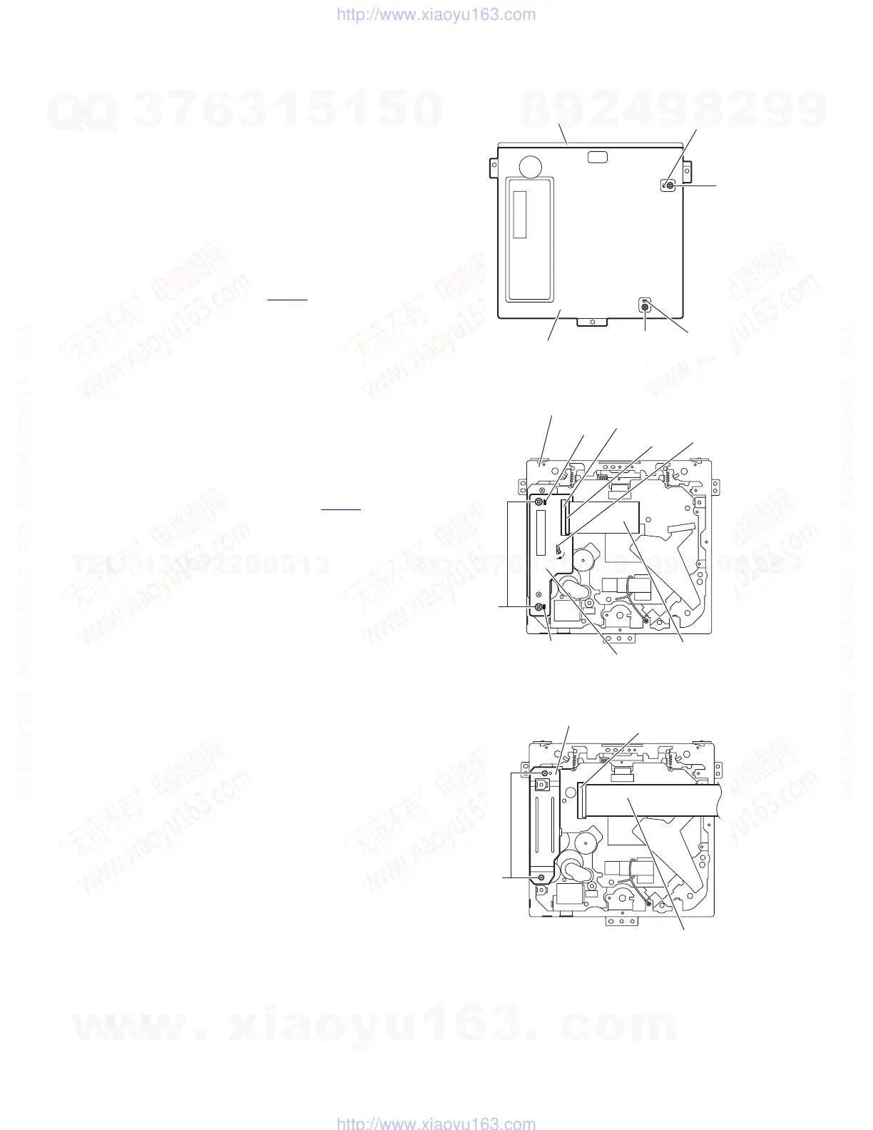
3.1.8 Removing the main sub board
(See Figs.9 to 11)
• Remove the front panel assembly, bottom cover, front chassis
assembly, side heat sink, main board and DVD mechanism as-
sembly.
(1) From the top side of the DVD mechanism assembly, re-
move the two screws L attaching the dust cover. (See
Fig.9.)
(2) Remove the dust cover from the DVD mechanism assem-
bly. (See Fig.9.)
Reference:
When attaching the dust cover, align the joints f in the
holes of the dust cover before attaching the screws L.
(See Fig.9.)
(3) Release the lock of the connector CN962
on the main sub
board and disconnect the card wire. (See Fig.10.)
(4) Bend the joint g in the direction of the arrow. (See Fig.10.)
(5) Remove the two screws M attaching the main sub board
and remove the main sub board from the DVD mechanism
assembly. (See Fig.10.)
Reference:
• When attaching the main sub board, align the joints h in the
holes of the main sub board before attaching the screws M.
(See Fig.10.)
• When the resolution of DVD mechanism assembly is done
sequentially, remove the two screws N attaching the support
bracket. (See Fig.11.)
• Remove the card wire from the connector CN401
as re-
quired. (See Fig.11.)
Fig.9
Fig.10
Fig.11
L
L
DVD mechanism assembly
Dust cover
f
f
Card wire
g
M
h
h
CN962
Lock
Main sub board
DVD mechanism assembly
Card wire
N
Support bracket
CN401
w
w
w
.
x
i
a
o
y
u
1
6
3
.
c
o
m
Q
Q
3
7
6
3
1
5
1
5
0
9
9
2
8
9
4
2
9
8
T
E
L
1
3
9
4
2
2
9
6
5
1
3
9
9
2
8
9
4
2
9
8
0
5
1
5
1
3
6
7
3
Q
Q
TEL 13942296513 QQ 376315150 892498299
TEL 13942296513 QQ 376315150 892498299
http://www.xiaoyu163.com
http://www.xiaoyu163.com