16
ENGLISH
Data Size: B6L (182 mm x 128 mm)
Book Size: B6L (182 mm x 128 mm)
This section is for the professional installer.
For safety’s sake, leave wiring and mounting to professionals. Consult the
car audio dealer.
WARNING
• The unit can only be used with a 12 V DC power supply, negative ground.
• Disconnect the battery’s negative terminal before wiring and mounting.
• Do not connect Battery wire (yellow) and Ignition wire (red) to the car
chassis or Ground wire (black) to prevent a short circuit.
• To prevent short circuit:
– Insulate unconnected wires with vinyl tape.
– Be sure to ground this unit to the car’s chassis again after installation.
– Secure the wires with cable clamps and wrap vinyl tape around the wires
that come in contact with metal parts to protect the wires.
CAUTION
• Install this unit in the console of your vehicle. Do not touch the metal parts
of this unit during and shortly after use of the unit. Metal parts such as the
heat sink and enclosure become hot.
• Do not connect the
wires of speakers to the car chassis or Ground wire
(black), or connect them in parallel.
• Connect speakers with a maximum power of more than 50 W. If the
maximum power of the speakers is lower than 50 W, change the
[AMPGAIN]
setting to avoid damaging the speakers. (Page 11)
• Mount the unit at an angle of less than 30º.
• If your vehicle wiring harness does not have the ignition terminal, connect
Ignition wire (red) to the terminal on the vehicle’s fuse box which provides
12 V DC power supply and is turned on and off by the ignition key.
• Keep all cables away from heat dissipate metal parts.
• After the unit is installed, check whether the brake lamps, blinkers, wipers,
etc. on the car are working properly.
• If the fuse blows, first make sure the wires are not touching car’s chassis,
then replace the old fuse with one that has the same rating.
Installation/Connection
Basic procedure
1 Remove the key from the ignition switch, then disconnect the
terminal of the car battery.
2 Connect the wires properly.
See “Wiring connection” on page 18.
3 Install the unit to your car.
See “Installing the unit (in-dash mounting)” on page 17.
4 Connect the terminal of the car battery.
5 Detach the faceplate and reset the unit. (Page4)
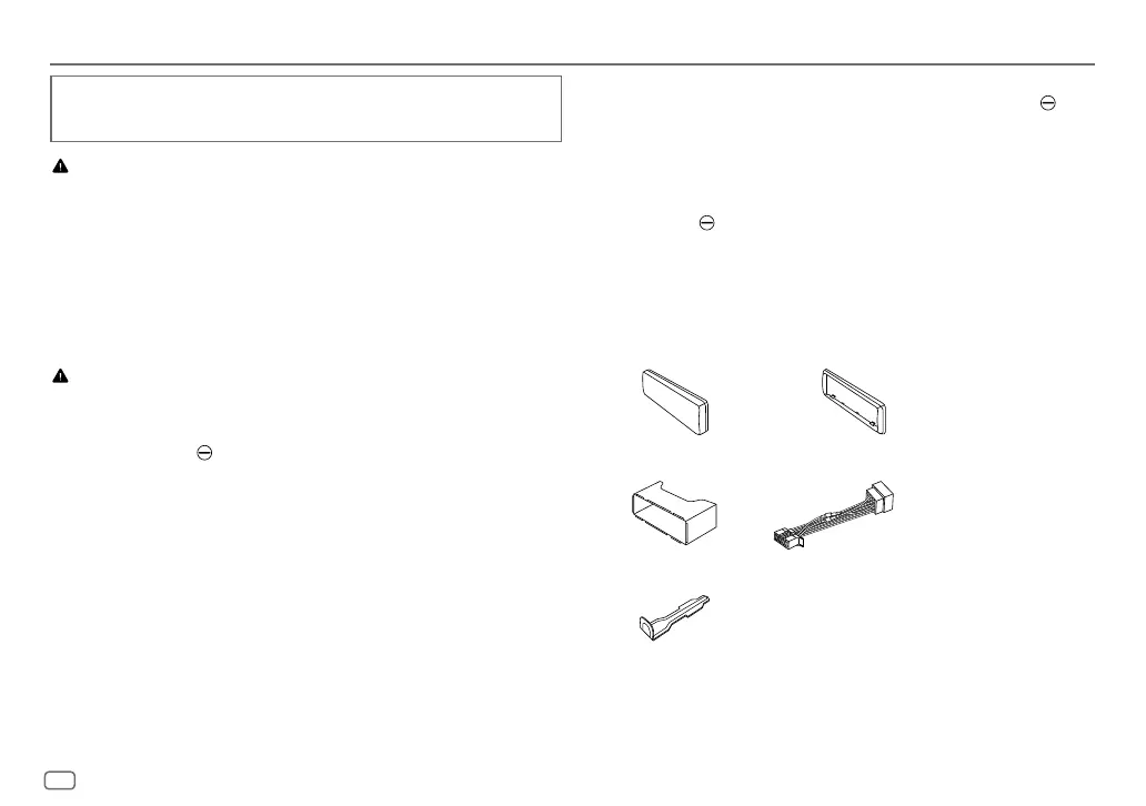
Part list for installation
(A)
Faceplate (×1)
(B)
Trim plate (×1)
(C)
Mounting sleeve (×1)
(D)
Wiring harness (×1)
(E)
Extraction key (×2)
JS_JVC_KD_X176_E_EN_int1.indd 16JS_JVC_KD_X176_E_EN_int1.indd 16 4/22/2019 10:14:38 AM4/22/2019 10:14:38 AM
 Loading...