..lye
LVT1908-001A
[J/E/U/US]
ENGLISH
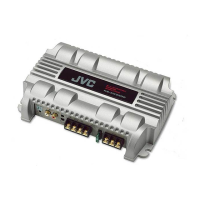
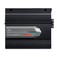
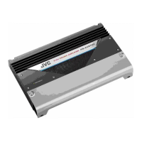
KS-AX3004
KS-AX3002
POWER
AMPLIFIER:
INSTRUCTIONS
AMPLIFICATEUR
DE
PUISSANCE:
MANUEL
D'INSTRUCTIONS
POWER SUPPLY
0508MNMMDWTKC
EN,
FR
© 2008 Victor Company of Japan, Limited
..
Not provided
Thank you for purchasing a
JVC
product. Please read
all
instructions carefully before operation, to ensure
your complete understanding and to obtain the best possible performance from the unit.
Forsafely. ...
•
Do
not raise the volume
level
too much,
as
this
will
block outside sounds. making driving dangerous.
• Stop the car before performing any complicated operations.
CAUTIONS AND NOTES
This unit is designed to operate on 12 V DC, NEGATIVE
ground
electrical
systems.
• This unit uses BTL (Balanced Transformerless) amplifier circuitry, Le., floating ground system.
so
comply with the following:
-
Do
not connect the "8"terminals of the speakers to each other.
-
Do
not connect the "8"terminals of the speakers to the metal body or chassis.
• Cover the unused leads with insulating tape to prevent them from short circuiting.
• When an extension lead is used, it should be as thick and short as possible; connect
it
firmly
with insulating tape.
•
Be
sure
to
leave an appropriate space between the antenna (aerial) and the wires of this unit.
• When replacing the fuse, only use
25 A fuses.
• Do not let pebbles, sand or metallic objects get inside the unit.
•
To
keep the heat dissipation mechanism running effectively, wipe the accumulated dust off
periodically.
• Listening to the tape, radio. CD or digital audio player, etc. with the volume set at a high level for
a long period of time will exhaust the battery. while the engine is turned off or while the engine
is idling.
• This unit becomes very hot. Be careful not
to
touch the unit not only when using but after using.
00
NOT disassemble the unit since there are no user serviceable parts Inside.
For
Customer
Use: Enter below the Model
No.
and Serial
No.
which are located on the top or
bottom of the cabinet. Retain this information for future reference.
il[:;~"[~
"r
>
::::::~
II'
I~'
I!J
I
*~
*
W 0
[[]
0 0
[I]
To
metallic body or
chassIs
2SAfuse * j
'*
(To
~n
ac.
c.essor
y
termlnal)@Remoteturn.online
~
..:
-~---
-----------
®
,------,
e 0
'-·,~;----·----l
---
---
12
V
(J;ii)
Ignition switch
j_
JVC
car
receiver, etc.
Car
battery
c:.
.
ImlllllI
To
prevent
short
circuits
while
making
connections,
keep
the
battery's
negative
terminal
disconnected.
OJ
Remote turn-on line (not provided)
®
When
you
use
a JVC
car
receiver
with
a
remote
lead. connect to the remote lead.
(QI
When
you
use
a
car
receiver
without
a
remote
lead, connect to the accessory circuit of
the car which is activated
by
the ignition switch.
In
this case, noise may occur when the car
receiver is turned
on
or off.
To
avoid this noise, do not turn on or off the car receiver itself.
You
can turn it on or off along with the on/off operation of the ignition switch.
rn
Ground lead (not provided)
rn
Power cord (not provided)
• When using a power cord, add a
25 A fuse near the battery as shown.
• Connect to the battery's
"Ef)"
terminal only after all the other connections have been made.
Model No.
INSTALLATION
Serial No.
The proper lead connected to each POWER terminal is as follows:
- +
Band
GND: AWG 8 to AWG 4 (The cross section is about 8
mm'to
21
mm'.)
- REM: AWG.18 to AWG 8 (The cross section is about 0.8
mm'
to 8
mm'.)
• Use ring terminals (not provided) for secure connection.
The following illustration shows a typical installation. However. you should make adjustments
corresponding to your specific car.
If
you have any questions or require information regarding
installation kits, consult your "JVC IN-CAR ENTERTAINMENT" car audio dealer or a company
supplying the kits.
£r~7::CS~J
Onto the trunk floor
Under the front seat
Mount
this
unit
on a
firm
surface,
such
as
in
the
trunk
or
under
the
front
seat.
• Since heat is generated
in
the unit, do not mount
it
near inflammable objects.
In
addition,
mount it
in
an
area that will not prevent the unit from dissipating the heat.
• Do not mount the unit
in
the places subject to heat: near a radiator.
in
a glove compartment
or
in
insulated areas such as under a car mat that will prevent the unit from dissipating heat.
• When mounting the unit under the front seat, make sure that adjusting the seat position will
not catch any wire of the unit.
y----
Provided screw
, $ 4 x
20
mm (13/16
in.)
When
mounting
this
unit, be
sure
to
use
the
provided
screws.
•
If
any other screws are used. there is a risk of loosening the unit or damaging the parts under
the car floor.
• Before drilling holes
in
the trunk to install the unit, make sure that there is a sufficient space
under the trunk so that you do not drill holes
in
the fuel tank. etc.
If
you have any questions regarding the thickness
of
the
power
cord, etc., consult your nearest
"JVC IN-CAR ENTERTAINMENT"
car
audio dealer.
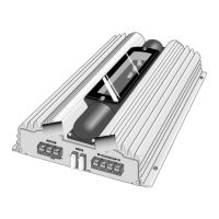
TERMINAL CONNECTIONS
When making terminal connections, properly fix each terminal with the
provided screw
by
turning it as illustrated.
• Use ring terminals (not provided) for secure connection.
Il!lmI
• Make sure the screw is fixed in place to prevent disconnections.
• Avoid over-tightening as
it
may cause the damage to the screw or its
head slot.
SPEAKER SYSTEMS
This amplifier provides two types of speaker connections: Normal Mode and Bridge Mode
connections.
You
can choose either type depending on the speakers equipped on your car.
Il!lmI
• Be sure not to connect the "8" terminals of the speakers to a common point.
•
If
the same lead is used for both left/right or front/rear speaker wirings. this unit cannot be used.
Always use the independent leads for each speaker.
In
this case. redo the wirings.
• Use the speakers with
an
impedance of 2 Q to 8 Q
(4
Q
to
8 Q: when used
in
Bridge Mode).
• Use the speakers which have sufficient capacity to the unit.
The proper lead connected to each SPEAKER OUTPUT terminal is AWG 18 to AWG
12 (The
cross section is about 0.8
mm'
to 3.3
mm').