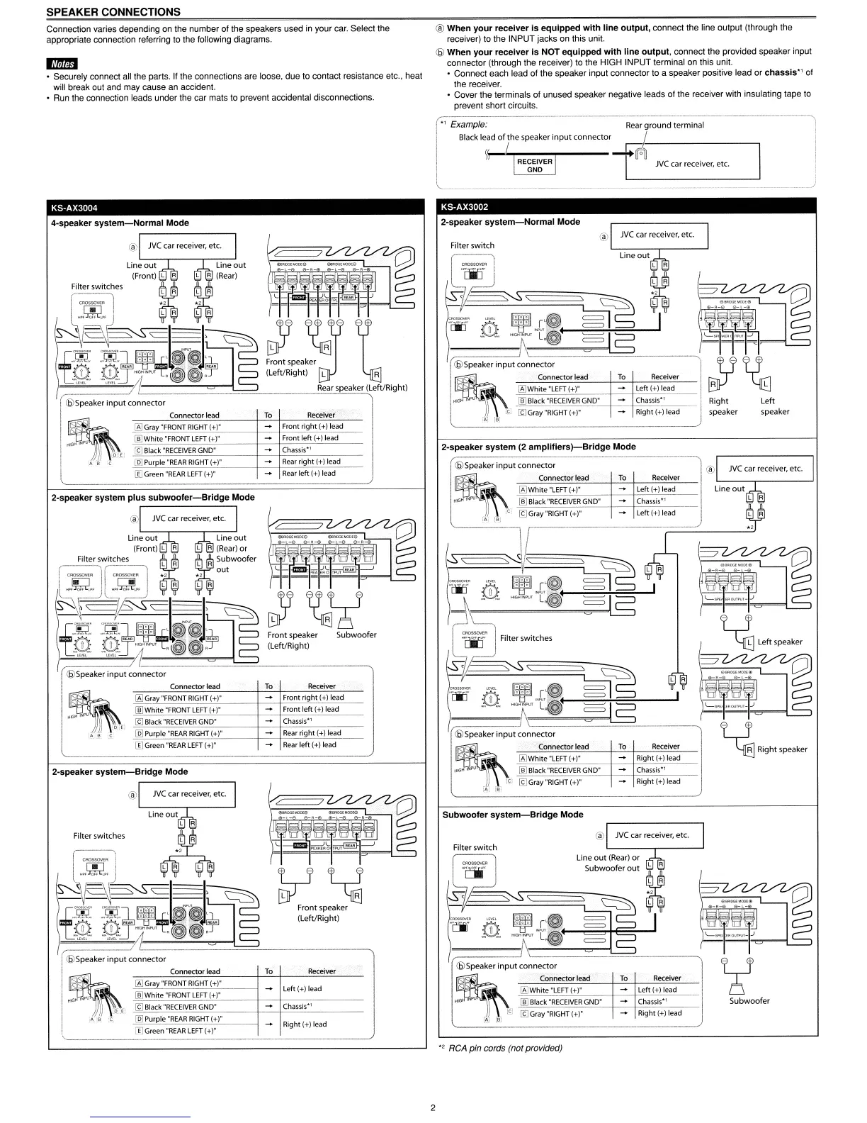
SPEAKER CONNECTIONS
Connection varies depending on the number of the speakers used in your car. Select the
appropriate connection referring to the following diagrams.
ED
• Securely connect all the parts. If the connections are loose, due to contact resistance etc., heat
will break out and may cause an accident.
• Run the connection leads under the car mats to prevent accidental disconnections.
®
When
your
receiver
is
equipped
with
line
output,
connect the line output (through the
receiver) to the INPUT jacks on this unit.
(@
When
your
receiver
is
NOT
equipped
with
line
output,
connect the provided speaker input
connector (through the receiver) to the HIGH INPUT terminal on this unit.
• Connect each lead of the speaker input connector to a speaker positive lead or
chassis"
of
the receiver.
• Cover the terminals of unused speaker negative leads of the receiver with insulating tape
to
prevent short circuits.
Subwoofer
~
Right speaker
JVC
car receiver,
etc
.
Left (+) lead
Chassis'
l
Ri9ht(+)I~
Left (+) lead
Left
(+) lead
Chassis·'
Rear
ground
terminal
To
Receiver
To
Receiver
=
=
=
\
®
Q9White
"LEFT
(+)"
llij
Black
"RECEIVER
GND"
!9Gray
"RIGHT
(+)"
Filter
switches
(6)Speaker
input
connector
Connector lead
Filter
switch
Filter switch
-S01-
,'-S
\
\~~
Y
~r'~
~~
;'[ifA
ifi
I
"'"~"""T.~
~5
(£)Speaker
input
connector
~
~-~,~
To
Receiver
Q9White
"LEFT
(+)"
-
Right (+) lead
INI'U _
(ID
Black
"RECEIVER
GND"
-
Chassis·'
Ie!
[9
Gray
"RIGHT
(+)"
-
Right (+) lead
-A"
re-
Subwoofer
system-Bridge
Mode
2-speaker
system
(2
amplifiers)-Bridge
Mode
•, Example:
Black lead
of
the speaker
input
connector
\~--++o
.
~
L-
---l
!
~~~\
~,
~
~
1-=
m
~
~
r'~
~5
I
-\~
__
"N<~.~
~
~'\'L"~t
~
5:::::-__
~I;;;"I;;;'I;;;"I~-'
I
(6)Speaker input connector
~
~-
~
~
Connector lead
To
Receiver
Q9White
"LEFT
(+)" Left (+) lead R L
HfGl"
I
[ID
Black
MRECEIVER
GND"
Chassis·!
Right
Left
Ie;
[gGray
"RIGHT
{+r
Right (+) lead speaker speaker
A
;9-
Subwoofer
Receiver
Rear
left (+) lead
Rear
right (+) lead
Front
right
(+) lead
Front left (+) lead
Chassis'!
Front
speaker
(Left/Right)
To
Connector lead
lID
Purple
"REAR
RIGHT
(+)"
Q9Gray
"FRONT
RIGHT
(+)"
!9
Black
"RECEIVER
GND"
llijWhite
"FRONT
LEFT
(+)"
Connector lead
To
Receiver
Q9
Gray
"FRONT
RIGHT
(+)"
-
Front right (+) lead
llijWhite
"FRONT
LEFT
(+)"
-
Front left (+) lead
!9
Black
"RECEIVER
GND"
-
Chassis·!
lID
Purple
"REAR
RIGHT
(+)"
-
Rear
right (+) lead
IIJGreen
"REAR
LEFT
(+)"
-
Rear
left (+) lead
Connector lead
To
Receiver
Q9
Gray
"FRONT
RIGHT
(+)"
-
left
(+) lead
llijWhite
"FRONT
LEFT
(+)"
io')
!9
Black
"RECEIVER
GND"
-
Chassis'!
,
lID
Purple
"REAR
RIGHT
(+)"
IIJGreen
"REAR
LEFT
(+)"
-
Right (+) lead
Filter
switches
[IJGreen
-REAR
LEFT
(+l"
(6)Speaker
input
connector
®
(£)Speaker
input
connector
®
~
, .
"~
;~~~~l~E'
".
,
Line
out
(Front) l A l A
(Rear)
or
Filter switches
~A
~R
Subwoofer
~
out
~
19:
:'~A
--
~I~
~I'
c::3
.D~~
-g:l,~~l~~J~
I-@
@J~.~L:~@)5"
~
A
.,
L R l R
\=~~
~
--
'----'
-----"
'----
= '
c::3
..em:
ml,~~~@~
I-@
@J~-L:~~Y
Line
out
(Front) l A
(Rear)
~
Fil::~r,:~tChes
~ ~
-~~
~
~
~
Ic::.c
~I~
~I'
c::3
.,[.~:
m:l,r~+IP~J~
I-@
@J;r~
"~~._
tli>Speaker
input
connector
" '
®
2-speaker
system-Bridge
Mode
4-speaker
system-Normal
Mode
2-speaker
system
plus
subwoofer-Bridge
Mode
",
RCA pin cords (not provided)
2
 Loading...