KS·AX3002
(lor
USA)
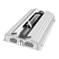
TROUBLESHOOTING
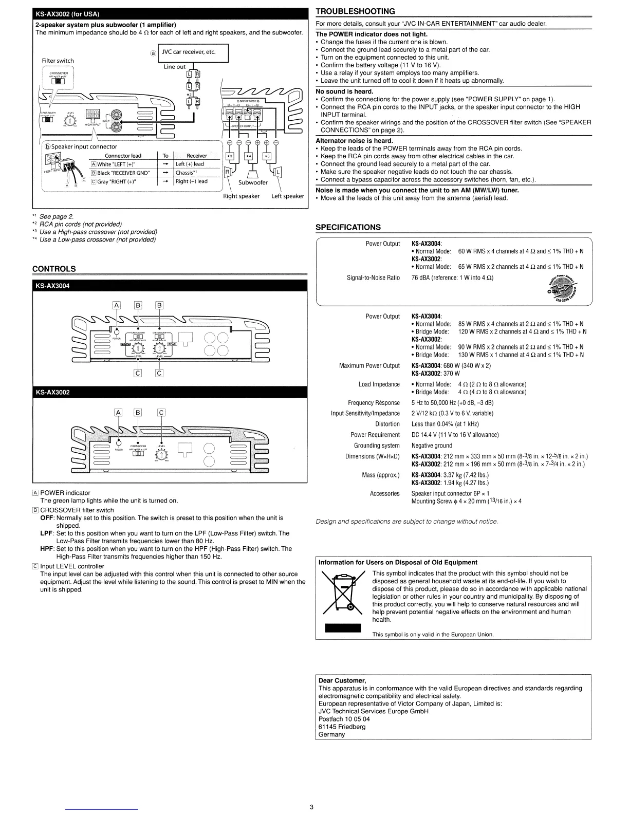
2-speaker
system
plus
subwooler
(1
amplilier)
The minimum impedance should be 4 0 for each
ollef!
and right speakers, and the subwoofer.
Alternator
noise
is
heard.
• Keep the leads of the POWER terminals away from the RCA pin cords.
• Keep the RCA pin cords away from other electrical cables in the car.
• Connect the ground lead securely to a metal part of the car.
• Make sure the speaker negative leads do not touch the car chassis.
• Connect a bypass capacitor across the accessory switches (horn, fan, etc.).
For more details, consult your "JVC IN-CAR ENTERTAINMENT"
car
audio dealer.
No
sound
is
heard.
• Confirm the connections for the power supply (see "POWER SUPPLY" on page 1).
• Connect the RCA pin cords to the INPUT jacks, or the speaker input connector to the HIGH
INPUT
terminal.
• Confirm the speaker wirings and the position of the CROSSOVER lilter switch (See "SPEAKER
CONNECTIONS" on page 2).
The
POWER
indicator
does
not
light.
• Change the fuses if the current one is blown.
• Connect the ground lead securely to a metal part
of
the car.
• Turn on the equipment connected to this unit.
• Confirm the battery voltage
(11
V to 16
V).
• Use a relay if your system employs too many ampliliers.
• Leave the unit turned off to cool
it
down if it heats up abnormally.
Noise
is
made
when
you
connect
the
unit
to
an
AM
(MW/LW)
tuner,
• Move all the leads of this unit away from the antenna (aerial) lead.
Left speakerRight speaker
@
I CROSSOItER
1-00
M
~~\
\
~
~
jEJ"-"g:;:i5~1
~[if"
~
¥
.C@
@
~
I
~~8l
1\U
-\~
LG
=
lS
~1~~~1
r::::--._-
j
L\
~~=='==!::::::::::~----!~
~
'l
I
<biSpeaker
input connector + - - + + -
'I
~G!
Connector lead
To
Receiver
*3
*4 *3
.
Q'
iAlWhite"LEFT(+)"
Left(+)
lead
IHIGH INP I,
"1ID=-"B"'la"'ck-'-""'R=EC"'E"'IV"'E"'R-G-N-O-"
-+--+-Ch"'a"'ss-is"'·"',
---
I R L
i . C
If]
Gray
"RIGHT
It)"
Right
It)
lead
\ Subwoofer r
",-
__
A B \ \
Filter switch
85
W
RMS
x 4
channels
at
2 Q
and
$1%
THO
t N
120
W
RMS
x 2
channels
at
4 Q
and
$1%
THO
t N
.,
See page
2.
"2
RCA pin cords (not provided)
"3
Use a High-pass crossover (not provided)
"'
Use a Low-pass crossover (not provided)
CONTROLS
KS·AX3004
SPECIFICATIONS
Power
Output
Signal-to-Noise
Ratio
Power
Output
Maximum
Power
Output
KS-AX3004:
•
Normal
Mode:
60
W
RMS
x 4
channels
at
4 Q
and
$1%
THO
t N
KS-AX3002:
•
Normal
Mode:
65
W
RMS
x 2
channels
at
4 Q
and
$1%
THO
t N
76
dBA
(reference:
1 W
into
4 Q)
KS-AX3004:
•
Normal
Mode:
•
Bridge
Mode:
KS-AX3002:
•
Normal
Mode:
90
W
RMS
x 2
channels
at
2 Q
and
$1%
THO
t N
•
Bridge
Mode:
130
W
RMS
x 1
channel
at
4 Q
and
$ 1%
THO
t N
KS-AX3004:
680
W
(340
W x
2)
KS-AX3002:
370
W
Design
and
specifications are
subject
to
change
without notice.
•
Normal
Mode:
4 Q
(20
to
8 Q
allowance)
•
Bridge
Mode:
4 Q
(4
Q
to
8 Q
allowance)
5
Hz
to
50,000
Hz
(to
dB,
-3
dB)
2
V/12
kQ
(0.3
Vto
6
V,
variable)
Less
than
0.04%
(at
1
kHz)
DC
14.4
V
(11
V
to
16
V
allowance)
Negative
ground
KS-AX3004:
212
mm
x
333
mm
x
50
mm
(8-
3
/8
in.
x
12-
5
/8
in.
x 2
in.)
KS-AX3002:
212
mm
x
196
mm
x
50
mm
(8-
3
/8
in.
x
7-
3
/4
in.
x 2
in)
KS-AX3004:
337
kg
(7.42
Ibs.)
KS-AX3002:
1.94
kg
(4.27
Ibs.)
Speaker
input connector
6P
x 1
Mounting
Screw
~
4 x
20
mm
(13/16
in.)
x 4
Mass
(approx.)
Accessories
Load
Impedance
Frequency
Response
Input Sensitivity/Impedance
Distortion
Power
Requirement
Grounding
system
Dimensions
(WxHxD)
Inlor'l'ation
lor
Users
on
Disposal
01
Old
Equipment
This symbol indicates that the product with this symbol should not be
disposed as general household waste at its end-of-lile. II you wish to
dispose
of
this product, please
do
so in accordance with applicable national
legislation or other rules in your country and municipality. By disposing of
this product correctly, you will help to conserve natural resources and will
help prevent potential negative effects on the environment and human
health.
KS-AX3002
!6J
POWER indicator
The green lamp lights while the unit is turned on.
@]
CROSSOVER filter switch
OFF: Normally set
to this position. The switch is preset to this position when the unit is
shipped.
LPF: Set to this position when you want to turn on the LPF (Low-Pass Filter) switch. The
Low-Pass Filter transmits frequencies lower than 80 Hz.
HPF: Set to this position when you want to turn on the
HPF
(High-Pass Filter) switch. The
High-Pass Filter transmits frequencies higher than 150 Hz.
[f]
Input LEVEL controller
The input level can be adjusted with this control when this unit is connected to other source
equipment. Adjust the level while listening to the sound. This control is preset to MIN when the
unit is shipped.
This symbol is only valid
in
the European Union.
Dear
Customer,
This apparatus is in conformance with the valid European directives and standards regarding
electromagnetic compatibility and electrical safety.
European representative of Victor Company
01
Japan, Limited is:
JVC Technical Services Europe
GmbH
Postlach 10 05 04
61145 Friedberg
Germany
3
 Loading...