13
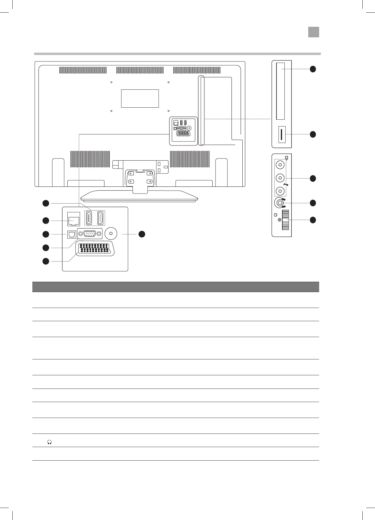
Rear View and Sockets
COMMON INTERFACE
USB
5Vdc
Max. 500mA
USB
5Vdc
Max. 500mA
SIDE AVYPbPr
MODE - / I
- +
SCART
SPDIF
Optic.OUT
VGA
ANT.
HDMI 1
(ARC)
HDMI 2
LAN
SCART
SPDIF
Optic.OUT
VGA
ANT.
HDMI 1
(ARC)
HDMI 2
LAN
3
4
5
2
1
6
Item Description
1 HDMI 1 & 2
Connects to a High-Definition (HD) signal output device, such as a set-top box, blu-ray
disc player or AV receiver.
2 LAN Connects to the internet for using the Smart hub.
3 SPDIF (Optic. OUT) Optical audio out (Digital) - Connects to an audio device via an optical cable.
4 VGA/YPbPr
Connects to a computer or other devices with a VGA interface.
The VGA input is also used for component input via a VGA to component cable (not
supplied).
5 SCART
Connects to a VCR, DVD Player, or other AV device with a SCART output socket.
Select SCART 1.
6 ANT Connects to the aerial socket on the wall with the RF coaxial cable.
7 COMMON INTERFACE Allows the insertion of a Common Access Module.
8 USB
Allows the insertion of a USB storage device to play video, audio, photo and text files
(USB mode) and record DTV programmes on to a USB storage device.
9 CVBS/AUDIO IN (L/R)
(audio L/R also used for YPbPr and VGA)
Connects to the Composite VIDEO and AUDIO (L/R) output sockets on external video
devices.
10
Connects to the headphones.
11 MULTI FUNCTION SWITCH Switches the TV into standby and on. Selects modes (channel,volume, and source).
7
8
9
10
11
COMMON INTERFACE
USB
5Vdc
Max. 500mA
LR
MODE - / I
- +
LT-32C672_IB.indd 13 26/07/2017 08:13
 Loading...