4-164-15
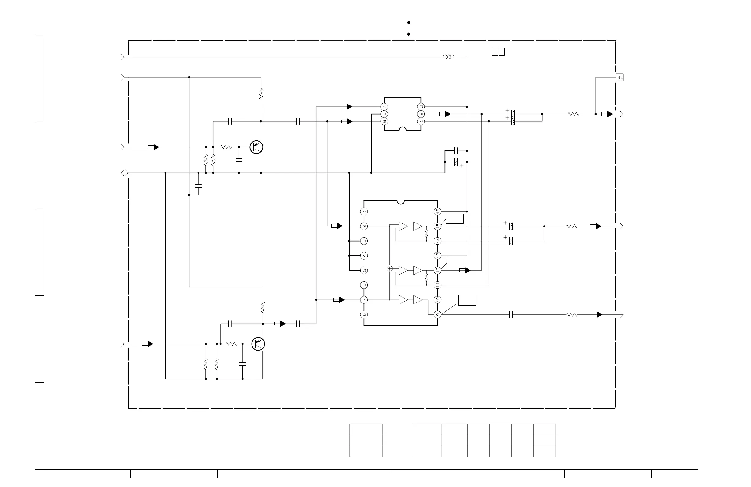
V OUT SCHEMATIC DIAGRAM4.7
HGFEDCBA
4
5
3
2
1
R4702
Q4702
R4708
CN25
C4714
R4707
R4701
SY_OUT
V_OUT
SC_OUT
C4706
R4703
R4709
C4716
C4703
C4717
R4710
IC4702
C4707
C4715
REG_4.8V
C4701
GND
CAM_Y
CAM_C
Q4701
IC4701
C4704
C4702
R4704
C4713
C4705
DAC_3.2V
L4701
C4709
R4712
R4706
R4713
C4708
750
1.1k
100µ
680
680
27p
15p
15p
1.2K
22µ
1µ
27p
1.2k
0.01
22µ
10µ
68
0.1
2SA1774/QR
/4
/6.3
2SA1774/QR
/6.3V
#
#
#
#
#
T
#
#
CIN
MUTE
GND
GND
JIG_CONN.
∗
V_OUT
GND
NC
NC
TO DSP
GND
TO DSP
YIN
Vcc
Chroma
MUTE
VCC
VCC
6dB
6dB
6dB
75
OUT
SAG
TO REG
TO REG
75
75
∗
∗
TO DSP
TO JACK
TO JACK
TO JACK
0 1 MAIN (V OUT)
y30153001a_rev0
C
Y+C
Y
Y
C
Y
C
C
C
Y
WF1
WF2
WF3
Y+C
Y+C
# : EXCHANGE PARTS LIST
IC4701 IC4702 R4712 R4713 C4713 C4714 C4715
VHS MODEL
SVHS MODEL
MM1512XN
BA7665FS 68 68 0.0122/6.3 100/4
∗
∗∗∗∗∗∗
NOTES : 1. The parts with marked ( ) is not used.
2. For V OUT waveforms, please refer to page 4-45.
∗
When ordering parts
,
be sure to order according to the Part Number indicated in the Parts List.
For the destination of each signal and further line connections that are cut off from
this diagram
,
refer to "4.1 BOARD INTERCONNECTIONS".
NOTES :
 Loading...