1-12 (No.MB638)
SECTION 2
SPECIFIC SERVICE INSTRUCTIONS
This service manual does not describe SPECIFIC SERVICE INSTRUCTIONS.
SECTION 3
DISASSEMBLY
3.1 Main body (Used figure are TH-D7E and TH-D7US)
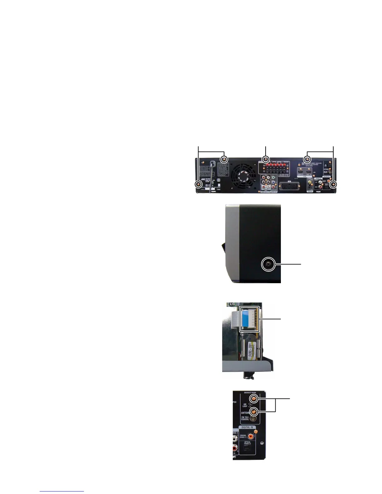
3.1.1 Removing the METAL COVER (See Fig.1, 2)
(1) Remove the four screws A attaching the METAL COVER.
(See Fig.1)
(2) Remove the one screw B attaching the METAL COVER.
(See Fig.1)
When remove the screw
B
use a screwdriver shown as
follows.
TORX Driver: size T10
Parts number: DR-L70
(3)
Remove the two screws
C
attaching the both side of
METAL COVER. (See Fig.
2
)
Fig.1
Fig.2
3.1.2 Removing the TUNER PACK (See Fig.3, 4)
(1) Disconnect the card wire from the MAIN BOARD assembly
connected to TUNER PACK. (See Fig.3)
(2) Remove the two screws D attaching the TUNER PACK.
(See Fig.4)
Fig.3
Fig.4
AAB
C
Tunerpack
connector
D
 Loading...