(No.MB638)1-15
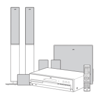
3.1.5 Removing the AMP BOARD assembly (See Fig.11)
(1)
Disconnect the connector wire from POWER BOARD
assembly connected to connector
CN501
of the AMP
BOARD assembly.
(2) Remove the one screw J attaching the EARTH WIRE from
FL BOARD assembly. (only European version)
(3) Remove the two screws K attaching the HEAT SINK
BRACKET.
(4) Remove the three screws L attaching the BRACKET.
(5)
Disconnect the connector
CN504
of the AMP BOARD
assembly connected to connector
CN514
of the CON-
NECTION BOAR assembly.
(6) Remove the CONNECTION BOARD assembly from MAIN
BOARD assembly.
Fig.11
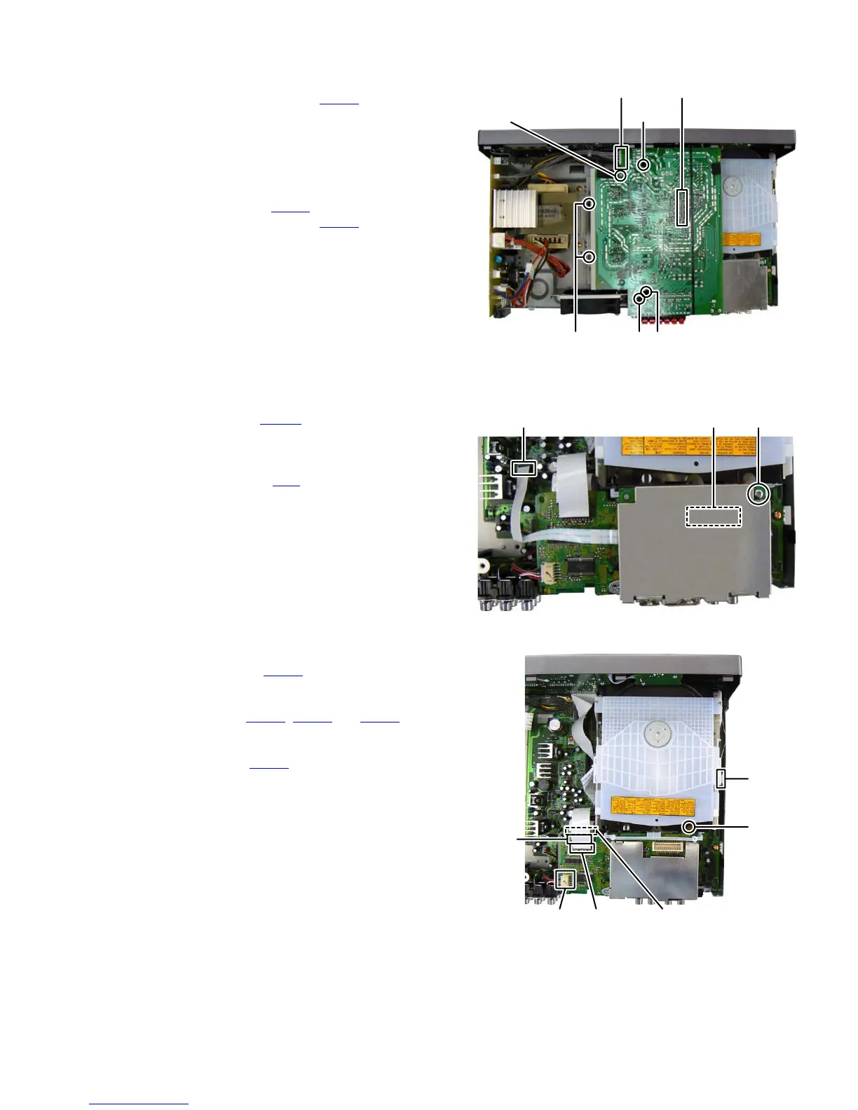
3.1.6 Removing the HDMI BOARD assembly (See Fig.12)
(1)
Disconnect the card wire from HDMI BOARD assembly
connected to connector CN203
of the MAIN BOARD
assembly.
(2)
Remove the one screw
M
attaching the HDMI BOARD
assembly.
(3)
Disconnect the connector CN2 of the HDMI BOARD
assembly connected to the DVD FRONT END BOARD
assembly.
Fig.12
3.1.7 Removing the DVD MECHANISM assembly (See Fig.13)
(1)
Disconnect the card wire from USB BOARD assembly
connected to connector
CN811
of the FRONT END
BOARD assembly.
(2) Disconnect the card wire from MAIN BOARD assembly
connected to connector CN701
, CN712 and CN801 of the
FRONT END BOARD assembly.
(3) Disconnect the card wire from LOADING BASE assembly
connected to connector CN212
of the MAIN BOARD as-
sembly.
(4) Remove the one screw N attaching the DVD MECHANISM
assembly.
Fig.13
JL
CN501 CN504
(Connection board
CN514 inside)
(only Europian
version)
KLL
CN2CN203
M
CN811 CN712
CN801
CN701
CN212
N
 Loading...