1-10
UX-A70MD
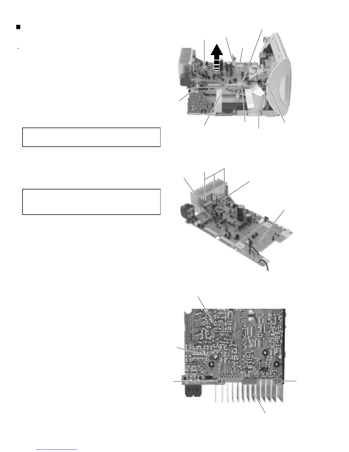
Removing the main board / heat sink
(See Fig.16 to 18)
Prior to performing the following procedure, remove
the rear cover, the side panels, thetop cover, the MD
mechanism assembly and the tuner & function
board.
Disconnect the wire from connector CN803, CN804
and CN806 on the main boardrespectively.
Disconnect the wire from W802 pin terminal.
Remove the screw I attaching the main board and
the screw J attaching the wireterminal.
1.
2.
Remove the three screws K on the heat sink bracket.
Remove the two screws L on the back of the main
board.
3.
4.
When reasse mbling, fit the slots of the
main board to the two bosses.
CAUTION:
When removing the heat sink bracket,
disengage the two joints d on theback of
the main board.
CAUTION:
CN806
CN804
I
CN803
Fig.16
Main board
Fig.17
Fig.18
L
Heat sink
K
Heat sink bracket
Main board
Main borad
Heat sink
L
J
Joint d
Bosse
Bosse
W802
 Loading...


