1-9
UX-A70MD
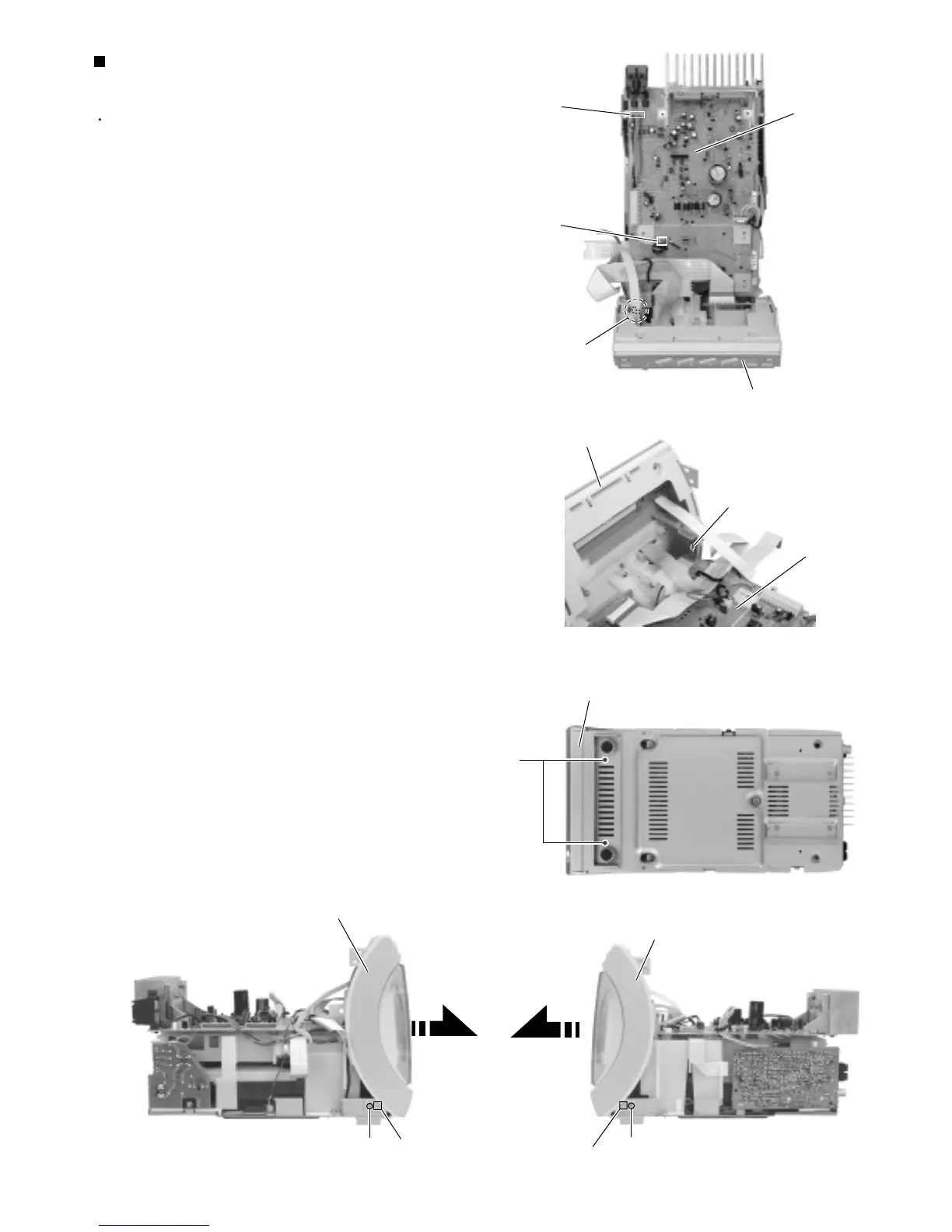
Removing the front panel assembly unit
(See Fig.11 to 15)
Prior to performing the following procedure, remove
the rear cover, the side panels, thetop cover, the MD
mechanism assembly and the tuner & function
board.
Disconnect the wire from connector CN804 and
CN806 on the main board. Disconnectthe wire from
W802 pin terminal.
Remove the two screws G on the bottom of the
body.
Remove the lower screw H on each side of the body.
Release the lower joint e on each side of the body.
Pull out the front panel assemblytoward the front.
1.
2.
3.
4.
Fig.11
Fig.12
G
CN804
CN806
Front panel assembly
Main board
Joint e
Joint e
Front panel assembly
Fig.15
Fig.13
Fig.14
Front panel assembly
Front panel assembly
W802
Front panel assembly
W802
Main board
H
H
 Loading...


