1-8
UX-A70MD
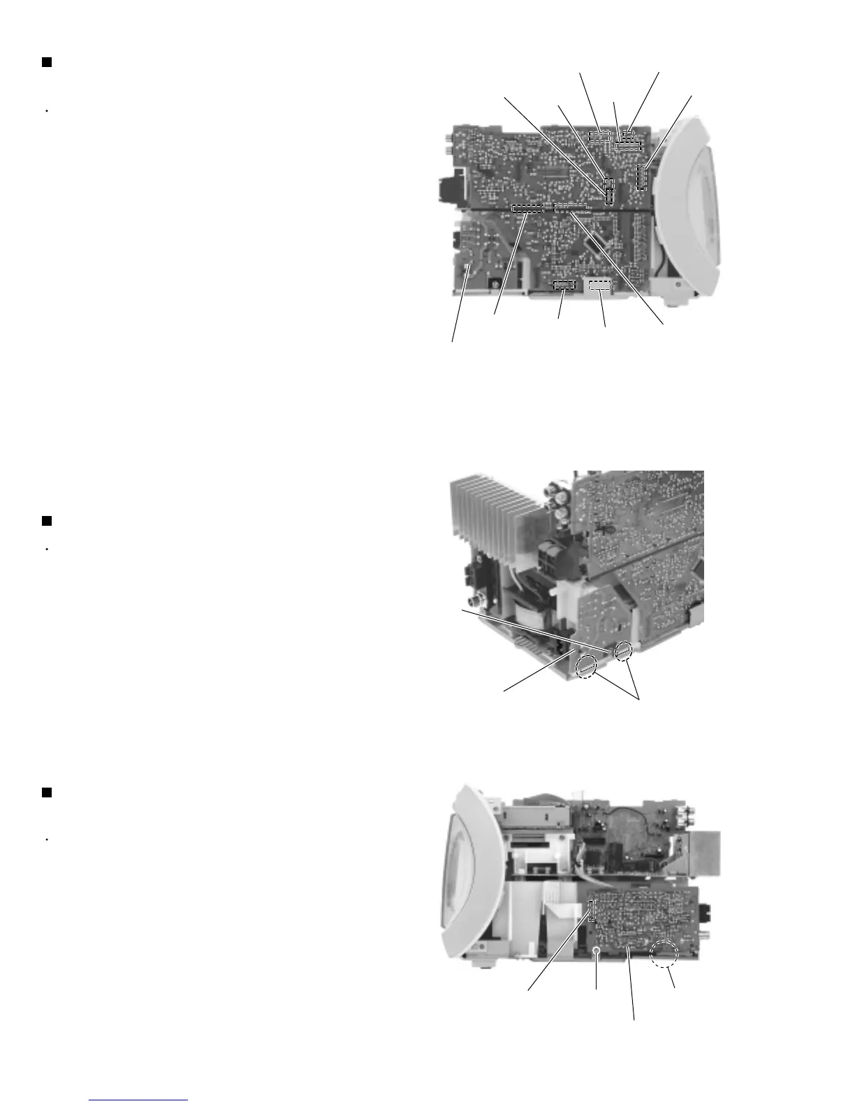
Removing the tuner & function board
(See Fig.8)
Removing the AC jack board (See Fig.9)
For the card wire connected to CN707,
disconnect it after performing the following
procedure 2 and 3.
CAUTION:
Prior to performing the following procedure, remove
the rear cover, the side panels and the top cover.
Disconnect the card wire from connector CN701,
CN705, CN707, CN708 and CN721 on the tuner &
function board on the right side of the body.
Similarly, disconnect the harness from CN706.
1.
2.
3.
Disconnect connector CN711 and CN712 on the
tuner & function board from CN801 and CN802 on
the main board by pulling them outward.
Disconnect connector CN703 and CN704 on the
tuner & function board from CN603 and CN604 on
the CD servo board by pulling them upward.
Prior to performing the following procedure, remove
the rear cover and the right side panel.
Remove the screw E on the right side of the body
and release the AC jack board from the two joints c.
Disconnect the harness from connector CN805 on
the AC jack board.
1.
2.
Removing the antenna terminal board
(See Fig.10)
Prior to performing the following procedure, remove
the rear cover and the left side panel.
Disconnect the card wire from connector CN1 on the
left side of the body.
Remove the screw F and release the antenna
terminal board from the joint d upward.
1.
2.
CN703
CN705
Fig.8
CN708
CN706
CN721
CN701
CN707
CN712
CN704
CN711
Joints c
E
AC jack board
CN1
F
Joint d
Antenna terminal board
Fig.9
Fig.10
AC jack board
 Loading...


