1-7
UX-A70MD
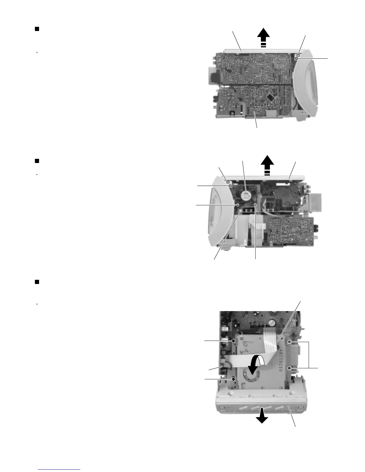
Prior to performing the following procedure, remove
the rear cover and the side panels.
Remove the two screws C on each side of the body.
Release the joint b on each side of the body and
remove the top cover backward and upward.
1.
2.
Removing the top cover
(See Fig.5 and 6)
Prior to performing the following procedure, remove
the rear cover, the side panels, the top cover and the
fan assembly.
Disconnect the card wire from connector CN721 on
the tuner & function board.
Remove the four screws D and the MD mechanism
assembly backward and upward while pulling the
front panel assembly forward.
1.
2.
Removing the MD mechanism assembly
unit (See Fig.7)
*Prior to performing the following procedure, remove
the rear cover, the right and left side panels.
Remove the two screws D on the right side of the
body and pull out the fan assembly sideward.
Disconnect the wire from connector CN807 on the
main board.
1.
2.
Removing the fan assembly (See Fig.6)
Fig.5
Fig.6
Joint b
C
Tuner & function board
Top cover
Joint b
Fig.7
D
D
D
MD mechanism assembly
Front panel assembly
C
Top cover
Fan assembly
D
D
CN807
CN721
 Loading...


