1-8 (No.MB408)
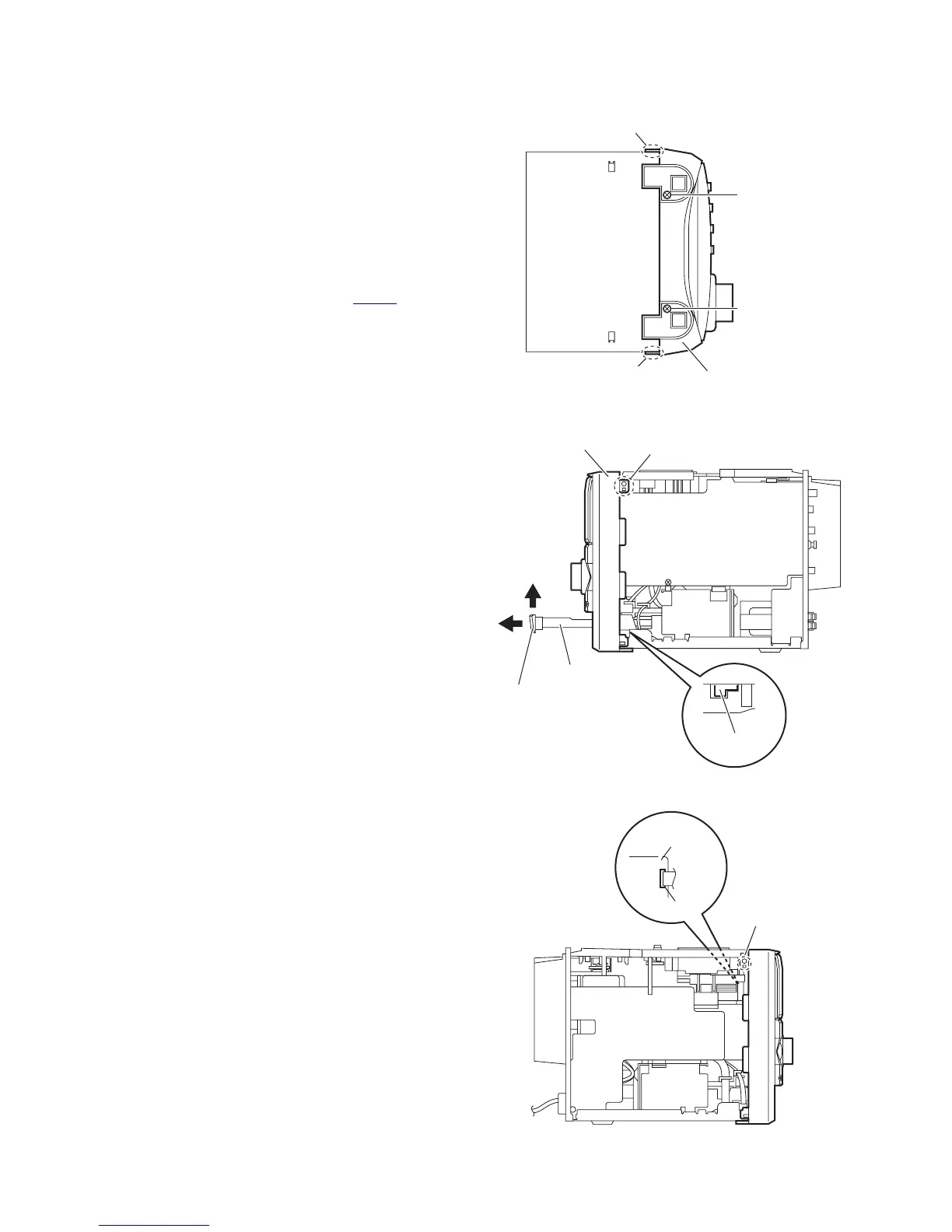
3.1.2 Removing the front panel assembly
(See Figs.4 to 6)
• Remove the metal cover.
(1) From the bottom side of the main body, remove the two
screws C attaching the front panel assembly. (See Fig.4.)
(2) From the right side of the main body, push the slide cam
and pull the tray assembly out of the main body in the di-
rection of the arrow 1. (See Fig.5.)
(3) Remove the tray fitting from the tray assembly in the direc-
tion of the arrow 2 and push the tray assembly in the main
body. (See Fig.5.)
(4) Release the claws a and claws b and remove the front pan-
el assembly toward the front. (See Figs.4 to 6.)
(5) Disconnect the card wire from the connector CN730
on the
micom board. (See Fig.6.)
Fig.4
Fig.5
Fig.6
Front panel assembly
C
C
a
a
1
2
Front panel assembly
Tray assembly
Tray fitting
Slide cam
b
Micom board
CN730
b
 Loading...