Installation Instructions Powador 2500xi / 3600xi / 4000xi / 4500xi / 5000xi_EN Page 11
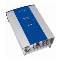
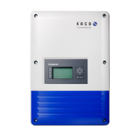
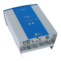
5 Device Description
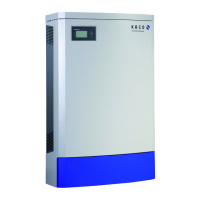
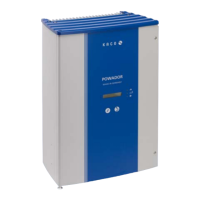
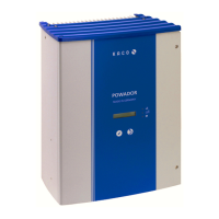
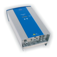
The transformerless Powador xi units are currently available
for fi ve different power ratings. The appropriate inverter type
is selected according to the maximum output of the pho-
tovoltaic modules that have been installed. The maximum
output values can be found in the data sheet (see Technical
Data, section 4).
Your inverter’s designation is located on the front side, above
the display and on the name plate.
5.1 Scope of delivery
– Powador
– Wall bracket
– Installation kit
– Documentation
5.2 Dimensioning the PV generator
The selection of the PV generator is of central importance
when dimensioning a PV installation. When doing so, you
must be sure that the solar generator is also compatible with
the inverter.
Observe the data provided in the data sheet (see Technical
Data, section 4) when dimensioning the solar generator.
Dimensioning the PV generator
The number of PV modules connected in series must be
selected in such a way that the output voltage of the PV gen-
erator stays within the permitted input voltage range of the
inverter - even during extreme outside temperatures. In Cen-
tral Europe, module temperatures between -10 °C and +70 °C
should be assumed. Depending on the way in which the modules
are installed and the geographic location, +60 °C or +70 °C
should be used when calculating the voltage. The tempera-
ture coeffi cients of the solar modules should be taken into
account. The following criteria must be met for calculating the
voltage of the PV generator:
– U
0
(-10 °C) < max. input voltage (800 V). Even at very low
outside temperatures (-10 °C), the no-load voltage of the
connected string must lie within the permitted input volt-
age range. If the temperature falls from 25 °C to -10 °C,
the no-load voltage in 12 V modules increases by approx.
2.8 V per module (5.6 V for a 24 V module). The no-load
voltage of the entire string must be less than 800 V
.
– U
Mpp
(+60 °C) > min. input voltage (350 V). Even at very
high outside temperatures (+60 °C), the MPP voltage of
the connected string should lie within the permitted input
voltage range. If the temperature increases from 25 °C to
60 °C, the MPP voltage in 12 V modules decreases by
approx. 3.6 V per module (7.2 V for a 24 V module). The
MPP voltage of the entire string should be at least 350 V.
If the MPP voltage moves outside of the permitted input
range, the installation still functions properly. In this situation,
the maximum possible amount of power is not fed into the
grid; instead, a small amount less is fed.
Provided that the input voltage is within the permitted input
voltage range, the inverter will not be damaged if a connected
PC generator provides current that is above the max. usable
input current.
If the PV generator briefl y provides more than the inverter’s
max. PV generator power, especially with changing cloud
cover and relatively low module temperatures, the inverter
may switch off due to safety reasons and automatically switch
on again after a country-specifi c waiting period (see section
4, Technical Data). The overload status is shown by a red LED
and as plain text on the display. Under normal circumstances,
the dynamic control of the inverter ensures that the inverter
continues to operate without interruption.
The solar generator still represents the largest factor in the
cost of a solar installation. For this reason, it is extremely
important to obtain maximum energy yields from the solar
generator. To achieve this, solar generators in Central Europe
should be oriented to the south at an angle of inclination of
30°. They should never be shaded.
This orientation is quite often not possible due to structural
reasons. In order to achieve the same energy yield as an opti-
mally oriented solar generator (south, 30° angle of inclina-
tion), the solar generator power can be increased.
For roofs with an east-west orientation, we recommend a
two-string PV installation. To achieve an optimum yield from
the installation, the fi rst string must be installed on the east
side of the roof; the second string on the west side.
For exposed locations in mountains or in southern regions,
we recommend that the power generator be reduced appro-
priately. Please consult with us or your specialty dealer about
this matter.
Section 5 · Device Description
CAUTION
Incorrect use is prohibited.
NOTE
KACOCALC Pro, a dimensioning program for the easy
selection of PV modules, can be downloaded at no cost
at the following address:
http://www.kaco-newenergy.de
 Loading...