Operating Instructions Powador 2500xi / 3600xi / 4000xi / 4500xi / 5000xi_EN Page 7
1
2
3
!
ok
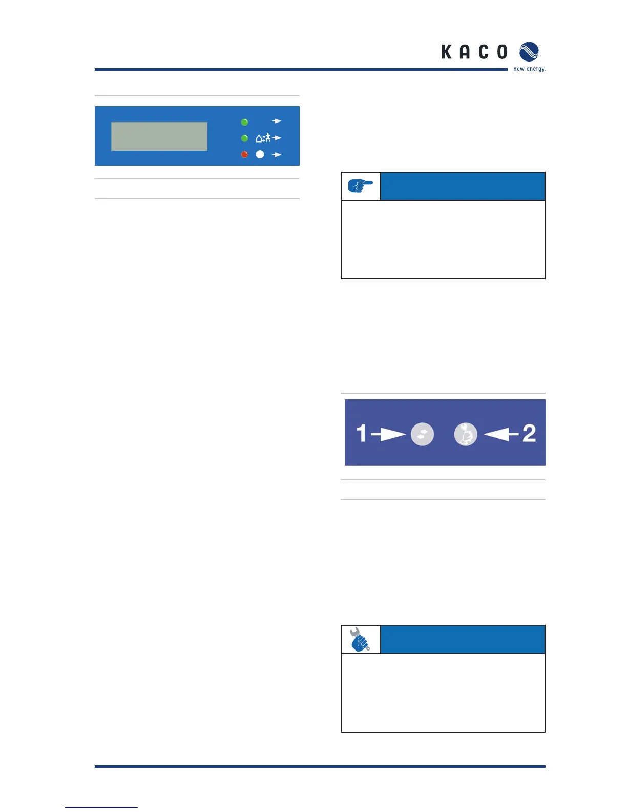
Figure 4.2: LED displays
LED (1) (green):
The LED begins to light up beginning with a photovoltaic
module voltage of approx. 300 V and goes out again if the
module voltage is lower than 250 V.
The “OK” LED indicates that the inverter and the inverter con-
trol are active. If this LED is not lit, the inverter cannot feed
into the grid.
In normal mode, the LED begins to light up in the morn-
ing (if there is enough sunlight) and goes out as nightfall
approaches.
LED (2) (green):
The LED lights up every time the inverter feeds into the grid. For
this to happen, the photovoltaic module voltage must exceed
400 V (factory setting) and suffi cient power must be provided
by the PV generator. If the grid feed is interrupted because the
power is too low, the inverter waits for a country-specifi c length
of time before it begins feeding into the grid once again. LED (2)
can, therefore, light up only when LED (1) is already lit.
In a normal state, the inverter begins feeding into the grid
in the morning and stops feeding into the grid as it becomes
increasingly darker. On cloudy days and in the winter months,
the grid feed can - depending on the PV generator and the
current grid feed power - be temporarily interrupted and sub-
sequently re-started. This process can repeat itself several
times, especially in the morning and evening. This is in no way
an indication of defective operation, but instead constitutes
normal operating behaviour.
LED (3) (red):
The LED indicates that the grid feed was stopped due to a
fault.
The following faults activate the LED (3):
– Grid overvoltage or undervoltage on one of the three
phases
– Failure of one of the phases L2 or L3
– Generator power is too high
– Shutdown due to the temperature being too high
– Fault in the unit
– Leakage current is too high (RCD type B)
– Overfrequency or underfrequency
– Insulation fault
– Communication error
– Fault in the DC grid feed
– Fault in the voltage transformer
– Selftest fault
– Fault in the RCD type B module.
Wait approx. 10 minutes to see if the fault is only temporary
in nature. If this is not the case, notify your authorised electri-
cian.
If the fault is cleared, the grid feed begins once again after a
country-specifi c waiting period (see Installation Instructions,
Section 4, “Technical Data”).
Check whether the fault in question relates to a general power
failure or whether the fuse between the meter and the inverter
has failed. If the fuse has failed, notify your authorised techni-
cian. If there was a power failure, simply wait until the fault
has been cleared. The system automatically re-starts.
4.3 Keys “1” and “2”
Figure 4.3: Powador control keys
Key “1” is used to switch between the various displays for
measured values and data. With key “2”, settings such as
those relating to the shutdown value can be confi gured. Here,
menu navigation is divided into two levels. In level 1 (display
mode), measured values such as the solar generator voltage
and yields can be read. Here, only key “1” is activated. In con-
fi guration mode, key “1” is also used to navigate through the
individual displays, and settings are confi gured with key “2”.
Section 4 · Operation
IMPORTANT
If the grid feed phase fails (power failure on the public
grid), LED (3) does not light up. If this happens, all LEDs
and the display go out. The inverter is shut down com-
pletely.
The inverter can only resume its normal operation when
the grid feed phase is available once again.
ACTION
By pressing key “1” for approx. 1 second, you can choose
which measured value is to be displayed.
The menus are continuous, which means that when you
arrive at the last entry in a menu, the fi rst entry is displayed
once again the next time key “1” is pressed (see Figure
4.4).
 Loading...