18 English
19 Suction bar
20 Suction bar clamping lever
21 Waste water tank cap
22 Fresh water tank filling hole
23 Filling system
24 Battery connector (with external charger)
Charger mains cable (with internal charger)
25 Accelerator pedal
26 Daytime running light
27 * Work light
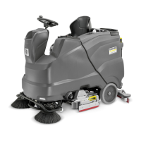
28 * Side scrubbing deck
29 Side brush (SB variant only)
30 Squeegee blade adjustment wheel (D cleaning
head only)
31 Cable hooks
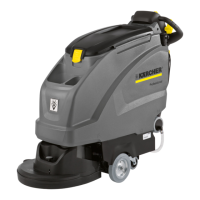
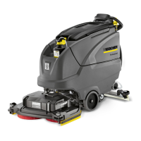
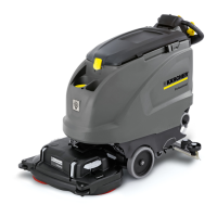
32 Cleaning head
33 Squeegee blade
34 Bearing cover (for brush replacement)
35 Brush replacement pedal (D cleaning head only)
36 Seat (with seat switch)
37 Seat adjustment lever
38 Battery
39 Type plate
40 Coarse dirt container (only with R cleaning head)
41 Fresh water tank cap with fresh water filter
* optional
Colour coding
● Control elements for the cleaning process are yel-
low.
● Control elements for maintenance and servicing are
light grey.
Control panel
Illustration B
1 Horn
2 Driving direction switch
3 Program switch
4 Safety switch
5 * Side scrubbing deck/side brush switch
6 Intelligent Key
7 Display
8 Info button
* optional
Program switch
Illustration C
1 OFF
Device is switched off.
2 Transport journey
Drive to the operating location.
3 Eco program
Clean the floor wet (with a reduced amount of water
and a reduced brush speed) and vacuum up waste
water (with reduced suction power).
4 Scour and vacuum
Clean the floor wet and vacuum up waste water.
5 Increased brush contact pressure
Clean the floor wet (with increased brush contact
pressure) and vacuum up waste water.
6 Scouring / pre-cleaning without vacuuming
Clean the floor wet and let the detergent act.
7 Vacuuming
Vacuum up the dirty waste.
8 Polishing
Polish the floor at a high brush speed without apply-
ing liquid.
Suction bar holder
● When driving through narrow spaces, the suction
bar can be removed and hung in one of the open-
ings on the lid of the waste water tank.
Illustration D
1 Suction bar
2 Mounting point
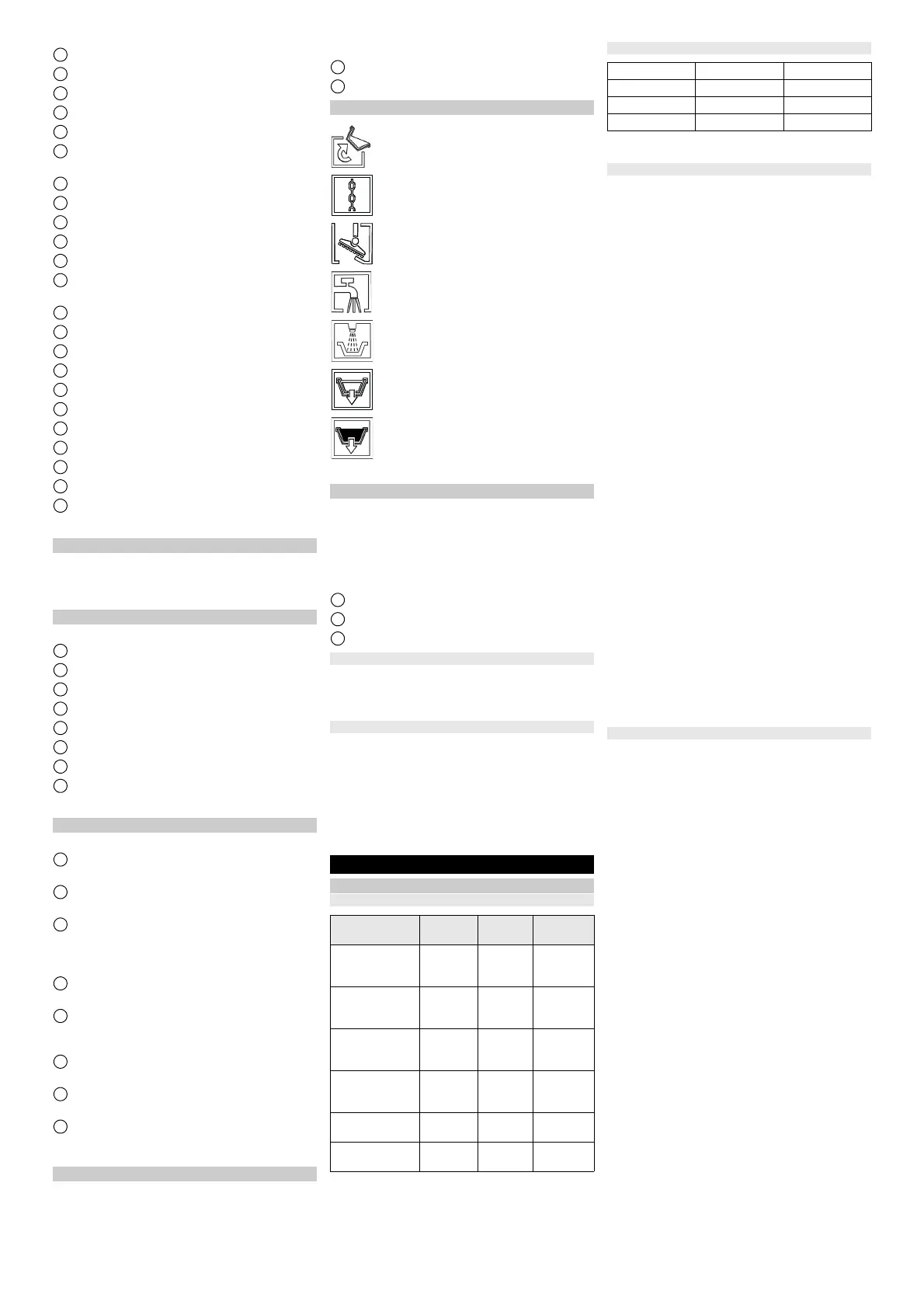
Symbols on the device
* optional
Overhead guard (option)
The overhead guard protects the driver of the device
from falling objects.
On devices with a overhead guard, the waste water tank
is equipped with a safety lock. This safety lock prevents
the waste water tank from pivoting back unintentionally
through forces acting on the overhead guard.
Illustration E
1 Overhead guard
2 Retaining plate
3 Locking screw M8x16, washer
Pivoting the waste water tank backwards
1. Empty the waste water tank.
2. Unscrew the locking screw.
3. Hold the waste water tank firmly and slowly pivot it
backwards.
Pivoting the waste water tank forwards
몇 WARNING
Risk of crushing
Body parts can become trapped between the device
and the waste water tank.
Make sure that there are no body parts between the de-
vice and the waste water tank when pivoting forward.
1. Hold the waste water tank firmly and slowly pivot it
forward.
2. Screw in and tighten the locking screw.
Installation
Batteries
Recommended battery sets
* Minimum volume of the battery charging room
** Minimum airflow between battery charging room and
environment
Maximum battery dimensions
* as with 4.654-306.7
** as with 4.654-307.7
Installing and connecting batteries
With the "Pack" variant, the batteries are already in-
stalled.
몇 CAUTION
Removing and installing the batteries
Unstable machine position
Ensure that the machine is positioned stably when re-
moving and installing the batteries.
ATTENTION
Incorrect connection polarity
Destruction of the control electronics
Take care to ensure the correct polarity when connect-
ing the batteries.
ATTENTION
Deep discharge
Risk of damage
Charge the batteries before starting the device.
1. Drain the waste water.
Note
For devices with a overhead guard, always observe the
notes in the "Overhead guard" chapter.
2. Pivot the waste water tank to the rear.
3. Fit the batteries in the device.
Illustration F
Illustration G
Illustration H
Illustration I
Illustration J
Illustration K
4. Connect the battery terminals using the connection
cables provided.
5. Clamp the supplied connecting cable to the (+) and
(-) battery terminals that are still free.
6. Check for correct installation of the pole protection
caps.
7. Connect the device-side battery connector to the
battery-side battery connector.
8. Pivot the waste water tank forwards and close it.
9. Set the battery type (see chapter "Gray Intelligent
Key").
ATTENTION
Risk of damage
The battery can be damaged by deep discharge.
Charge the battery before initial startup of the device.
Charging the battery
Note
The device has deep discharge protection, i.e. the de-
vice can only be driven when the permitted minimum ca-
pacity level is reached. "Charge Battery" and "Charge
Battery" appear in the display.
When using other batteries (e.g. from other manufactur-
ers), the deep discharge protection for the respective
battery must be reset by Kärcher Customer Service.
DANGER
Inappropriate use of the charger
Electric shock
Adhere to the mains voltage and fuse values specified
on the device type plate.
Only use the charger in dry rooms with sufficient venti-
lation.
Flammable gases are generated when the battery is
charged
Risk of explosion
Only charge the batteries in a suitable room. The room
must have a minimum volume depending on the battery
type and an adequate air exchange rate with a minimum
air flow (see "Recommended batteries").
ATTENTION
Accumulation of dangerous gases under the tank
during the charging process
Risk of explosion
Pivot the waste water tank upwards before charging
low-maintenance batteries.
Note
The average charging time is approx. 10-12 hours.
The recommended chargers (for the respective batter-
ies) are electronically controlled and stop the charging
process automatically.
The device cannot be used during the charging pro-
cess.
1. Drive the device directly to the charger and do not
drive on slopes.
Handle for pivoting up the waste water tank
Lashing point
* Mop holder
* Filling system water connection
* Waste water tank flushing system water
connection
Fresh water tank drain opening
Waste water tank drain opening
Description Order no. Volume
(m
3
)*
Airflow
(m
3
/h)**
Battery set 240
Ah, trough, low
maintenance
4.035-
987.7
27 10.8
Battery set
180Ah, trough,
low maintenance
4.035-
988.7
20.25 8.1
Battery set
240Ah, 6 blocks,
maintenance-free
4.654-
306.7
6.975 2.79
Battery set
180Ah, 6 blocks,
maintenance-free
4.654-
307.7
5.175 2.07
Battery set 285
Ah AGM
4.654-
057.7
8.91 3.56
Battery set 170
Ah AGM
4.654-
061.7
24.75 9.9
Layout A* B**
Length 244 mm 312 mm
Width 190 mm 182 mm
Height 275 mm 365 mm
 Loading...