EasyManuals Logo

Kenmore 111.72695120 User Manual

Kenmore 111.72695120
79 pages
To Next Page IconTo Next Page
To Previous Page IconTo Previous Page
Page #23 background imageLoading...
Page #23 background image
6. Wiring Diagram
To avoid risk of electrical shock that can cause death or severe personal injury,
disconnect unit from power before servicing unless tests require power.
23 / 69
!
WARNING
CN 12 of PCB Main (Inner Control Panel)
Item
Pin No
On
Off
Remarks
Voltage(V)
frequency(Hz)
Voltage(V)
frequency(Hz)
RX, TX
1,2
0~5V Swing
-
-
-
Immeasurable
Power
3,4
12
-
-
-
Always on
This control panel is located inside the hinge cover.
On the SVC Parts list, it is stated as " A10 "COVER HI *T AS"
How to diagnose if not working :
Check whether there is any missing connector connection or any wiring problem, if the problem still persists, then replace
the hinge cover. The way to replace the hinge cover is in section 11-19 (Freezer, Pantry and Refrigerator Door Switches)
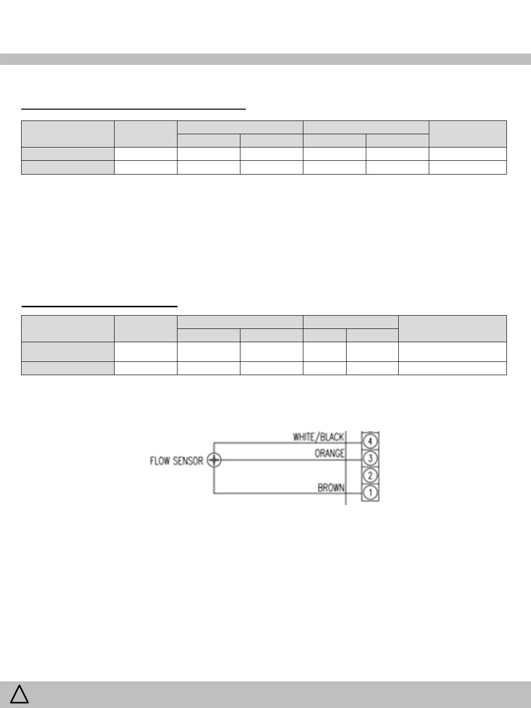
CN 7 of PCB Main (Sensors)
Item
Pin No
Flowing
No Flow
Remarks
Voltage(V)
frequency(Hz)
Voltage(V)
frequency(Hz)
Flow Sensor Power
1,4
~ 2.5V
*
0 or 5v
0
* Based on water pressure/
flow-rate
Flow Sensor Signal (FG)
1,3
5V
n/a
5v
n/a
Always on
Temperature sensors (Pins 5 -20) See Sensor Tables for voltage and resistance values at temperatures
Signal
5V
GND

Questions and Answers:

Question and Answer IconNeed help?

Do you have a question about the Kenmore 111.72695120 and is the answer not in the manual?

Kenmore 111.72695120 Specifications

General IconGeneral
BrandKenmore
Model111.72695120
CategoryRefrigerator
LanguageEnglish

Related product manuals