Adjustments
All the circuits of
AG-203
are factory adjusted
prior
to shipment and no further adjustments are required, ex-
cept for the frequency dial which may need readjust-
ment for proper tracking. Although this dial is
also
pre-
adjusted at the factory. If readjustment is required,
proceed to the adjusting work using an accurate test
equipment. Note that the power supply voltage must be
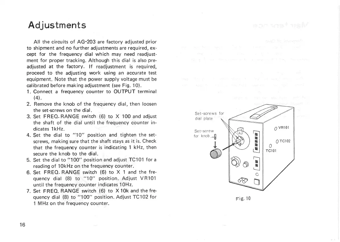
calibrated before making adjustment (see Fig. 10).
1.
Connect a frequency counter to
OUTPUT
terminal
(4).
2.
Remove the knob of the frequency dial, then loosen
the
set-screws
on the dial.
3.
Set
FREQ.
RANGE
switch (6) to X 100 and adjust
the shaft of the dial
until
the frequency counter in-
dicates
1kHz.
4.
Set the dial to "10" position and
tighten
the set-
screws,
making sure that the shaft
stays
as it is.
Check
that the frequency counter is indicating 1 kHz, then
secure
the knob to the dial.
5.
Set the dial to "100" position and adjust TC101 for a
reading of 10kHz on the frequency counter.
6.
Set
FREQ.
RANGE
switch (6) to X 1 and the fre-
quency
dial (8) to "10" position. Adjust VR101
until
the frequency counter indicates 10Hz.
7.
Set
FREQ.
RANGE
switch (6) to X10k and the fre-
quency
dial (8) to "100" position. Adjust
TC102
for
1
MHz on the frequency counter.
FIG-
10
16
Set-screws
for
dial plate
Set-screw
for knob

 Loading...


