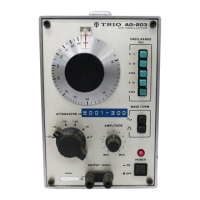
Panel
Controls and Their Functions
The
table below describes the functions of panel
controls. Refer to the panel diagram on page 9.
FRONT
PANEL
1.
This lamp
(light
emitting
diode) lights when
POWER
switch (2) is ON.
2.
POWER
Pushbutton type switch turns on the power when
pressed.
3.
ATTENUATOR
6-position
output
attenuator selects attenuations
of OdB to -50dB in 10dB steps.
4.
OUTPUT
Output
terminal used for
both
sine wave and
square
wave. The marking indicates GND
(case
grounded).
5.
WAVE
FORM
Output
waveform selector switch. When pressed
to " V,
output
signal is sine wave. When pressed
to
"-TL"
the signal is square wave.
6.
FREQ.
RANGE
Oscillating frequency range selector switch which
selects
the ranges in 5 steps as follows:
x
1 10Hz - 100Hz
x
10 100Hz- 1kHz
x
100 1 kHz - 10kHz
x
1k 10kHz- 100kHz
x
10k 100kHz- 1MHz
7.
AMPLITUDE
Amplitude adjuster to continuously vary the
amplitude of
output
voltage.
8.
FREQUENCY
DIAL
This
dial adjusts oscillating frequencies. Frequen-
cies
can be read by
multiplying
the reading on the
dial
scale
by magnification of
FREQ.RANGE,
9.
DIAL
SCALE
This
dial is calibrated
with
graduations of 10—100
to indicate oscillating frequencies.
10.
DIAL
POINTER
This
pointer
indicates frequencies on the dial
scale.
8

 Loading...