EasyManuals Logo

Kenwood KT-7020 Service Manual

Kenwood KT-7020
32 pages
To Next Page IconTo Next Page
To Previous Page IconTo Previous Page
Page #12 background imageLoading...
Page #12 background image
KT-7020
|
~
KT-7020
ADJUSTMENT
ADJUSTMENT
INPUT
OUTPUT
TUNER
ALIGNMENT
OUTPUT
TUKER
TEM
SETTINGS
SETTINGS
SETTINGS
POIATS
ALIGN
FOR
SETTINGS
SETTINGS
Unless
otherwise
cpecified,
the
individual
switches
should
be
set
as
following:
(a)
98.
0MH2
ALIGHMENT
POINTS
ALIGN
FOR
$8.
OMEz
SELECTOR:
L
or
&
kHz,
£68.
25kHz
dev
SELECTOR:Fi
IF
BAND:¥iDE
RF
SELECTOR:DISTANCE
TUNING
MODE:AUTO
REC
CAL:
OFF
Connect
a
DC
PROGRAM:
OPP
Wininua
distortion.
BAND
EDGE
-
voltmeter
between
|
TUNING
MODE:
Pilot:
46.
75kHz
dev
ie)
TP3CV¥T)
and
TP4(GHD).|
MARU
87.
SWH2
80dBu(ANT
input)
Connect
a
DC
{C)
BAND
EDGE
~
voltmeter
between
|
TUNING
MODE:
TCL
DISTORTIONCT)
98.
OWHz
TP3CVT)
and
TPACGHD)
MANU
108, OMHZ
STEREO
SELECTOR:
L
or
R
98.
OMHz
¥R2
:
;
Repeat
alignaents
1
and
2
several
tim
NARROW
1kHz,
£68.
25kHz
dev
(B)
IP
BAND:
x88-)
Mininua
distortion.
th)
(E
&
T
types)
|
Pilot:46.75kHz
dev
NARROW
98.
OM
Connect
a
DC
80dBu(ANT
input)
DISCRIMINATOR
0
dev
voltmeter
between
98,
Oz
0.000Vti0a¥
Repeat
the
adjustuents
from
I0
to
15
a
few
tiaee
to
miniaize
the
distortion.
100dBuCANT
input)
{TPSCAFC)and
TP6CYREF)
|
(c)
79)
Connect
98.
0MH2
98.
OMl2
a
DC
voltaeter
SEPARATION
SELECTOR:
R
vR4
PLL
DETECTOR
0
dev
between
TPT(¥CC/2)
0.
000¥420a¥
a)
1kHz,
#68.
25kHz
dev
(8)
98.
OWBz
(X05-)
Minimua
crosstalk.
100dBuCANT
input)
and
TP8(DET).
Ro-L
Pilot:
t6.75kHz
dev
a)
Connect
|
"esa
input)
98.
OMHz
a
frequency
counter
(c)
|
0
dev
between
ms
|
19.
000kHz+108z
98.
O4RZ
1004BuCANT
input)
and
TP20(¥CO).
SEPARATION
SELECTOR:
L
vRS
(a)
Waxiaua
aaplitude
@
1kHz,
268.
25kHz
dev
(B)
98.
MHZ
(x05-)
Miniaua
crosstalk.
RF
ALIGNMENT
98.
OMHz
(BY
98.
OMHz
Lt.4,7,10
and
cyametry
Pilot:
+6.75kHz
dev
Iktiz,
475kH2z
dev
x
Repeat
the
sequence
from
LI--L4—-L?—--L10--L1+:-
+
--
[o)
Maxiaua
amplitude
iFTCL)
98,
O¥Hz
(B)
98.
ONHZ
Lit
and
syasetry
kHz,
+75kHz
dev
(x05-)
of
the
oscilloscope
display,
(A)
Maxiaum
auplitude
8
IFT(2)
98.
OWHz
(B)
98.
OMHz
and
syasetry
kHz,
+75kHz
dev
of
the
oscilloscope
display.
(A)
Position
where
the
STEREO
98.
OMliz
indicator
lights
SELECTOR:
MAIN
-
98.
OMRz
when the
control
is
of
the
oscilloscope
display.
80dBu(ANT
input)
Repeat
the
adjustments
of
16
and
17
a
few
times
so
that
the
B-to
AM
SECTION
Keep
the
All
loop
antenna
installed.
SELECTOR:
AM
TUNING
KODE:AUTO
REC
CAL:OFF
PROGRAM:
OFF
Connect
a
DC
voltmeter
between
TP3CVT)
and
TP4CGRD)
Connect
s
DC
voltmeter
between
TP3(¥T)
and
TPACGND).
Repeat
alignments
[1]
and
{2}
several
tines.
-L
and
L-to-R
separations
are
equal.
530kHz
161
0kHz
9
AUTO-STOP
SENSITIVITY
lkHz,#75kW2
dev
(X86-)
rotated
gradually
clockwise
(D)
w
Maxisua
amplitude
J2dBuCANT
input)
from
the
sost.
RF
ALIGNMENT
630kHz
(BD
630kH2
and
symmetry
a
a)
400Hz,30%_
nod
(x05-)
of
the
oscilloscope
display
|
98.
OMNZ
(b>)
&
iz
Maxinua
amplitude
DISTORTION(1)
|
SELECTOR:
MONO
(8)
98.
OWHz
Miniaua
distortion.
RF
ALICKMENT
]
.
1440kH2
()
1440kHz
Tez and
syanetry
DET
1kHz,
+75kHz
dev
>
400H2,30%
aod
of
the
oscilloscope
display.
B0dBuCANT
input)
ts
[3]
and
[4]
several
tines.
(©)
®)
ww
Maximus
anplitude
98.
OMHz
999kH2
(B)
999kHz
and
syanetry
DISTORTION(2)
SELECTOR:
WONO
(B)
Winimus
distortion.
of
the
oscilloscope
display.
400H2,30%
od
@
L28
has
been
preset
so
the
adjustaent
is
usually
not
required.
vr
The
peak
will
be
easier
to
locate
if
the
test
loop
antenna
is
used.
WON0
kHz,
+75kHz
dev
*
80dBu
(ANT
input)
()
98.
OMHz
SELECTOR:
MONO
1kHz,+75kH2
dev
%*
80dBu(ANT
input)
Adjust
10,
11
and
12
alternately
a
few
tines
to
ainiaize
the
MOKO
distortion.
*
EAT
types:
ikiz,
t46kHz
dev.
)
98.
OMHz
SELECTOR:
SUB
kHz,
£68.
25kHz
dey
Pilot:26.75kHz
dev
S0dBu(ANT
input)
©)
98.
OMHz
SELECTOR:
SUB
IkHz,
t68.25kHz
dev
Pilot:26.75kEz
dev
8OdBuCANT
iaput)
After
the
adjustment
of
14,
DISTORTIONC3)
WONO
98.
OMHz
Minieum
distortion.
DISTORTIONC4)
STEREO
(8)
98.
OMEz
Miniaum
distortion,
DISTORTIONCS)
STEREO
Winieus
distortion.
adjust
13
again
to
sinimize
the
distortion
at
1kHz.
20
21

Other manuals for Kenwood KT-7020

Questions and Answers:

Question and Answer IconNeed help?

Do you have a question about the Kenwood KT-7020 and is the answer not in the manual?
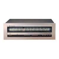
Kenwood KT-7020 Specifications

FM Tuner Section IconFM Tuner Section
tuning frequency range87.5 MHz - 108 MHz
usable sensitivity (MONO)0.95 µV/10.8 dB
total harmonic distortion (MONO)0.007%
signal to noise ratio (MONO)92 dB
stereo separation (1 kHz)65 dB
capture ratio1.0 dB (WIDE)
alternate channel selectivity (+400 kHz)60 dB (WIDE)
image rejection ratio (at 98 MHz)82 dB
IF rejection ratio (at 98 MHz)110 dB
spurious rejection ratio (at 98 MHz)105 dB
AM suppression ratio76 dB
frequency response20 Hz - 15 kHz, +0.5 dB, -0.5 dB
output level/impedance0.6 V/3.3 kΩ
AM Tuner Section IconAM Tuner Section
tuning frequency range531 kHz - 1, 602 kHz
usable sensitivity10 µV (350 µV/m)
signal to noise ratio55 dB
total harmonic distortion0.25%
image rejection ratio (Loop)40 dB
selectivity30 dB
output level/impedance0.18 V/3.3 kΩ
General IconGeneral
power consumption20 W
dimensions (W x H x D)440 mm x 98 mm x 318 mm
weight4.3 kg

Related product manuals