33
EN
33
3 - PRELIMINARY CHECKS
4 - LIST OF CABLES REQUIRED
Before installing the product, perform the following checks and in-
spections:
- make sure that the product xing zone is not subject to ooding;
- check that the electricity supply line to which the product is to be
connected is suitably earthed and protected by an overload and dif-
ferential safety breaker device;
- the system power supply line must include a circuit breaker device
with a contact gap allowing complete disconnection in the conditions
specied by class III overvoltage;
- ensure that all the material used for installation complies with the
relevant regulatory standards;
- Please refer to Fig. 1 and in particular to the table with the nomen-
clature of the main parts to which reference will be made throughout
this manual.
- Please refer to Figs. 2 and 3 showing the overall dimensions and
the typical installation diagram of an automation system for road bar-
rier.
Before powering and starting up the product, check and verify the
following points:
- check that the manual movement of the barrier is smooth and free
from higher friction areas and jamming;
- check that the barrier bar, moved manually, is still balanced if incli-
ned to an angle of 45°..
Warnings:
- high acidity or salinity or nearby heat sources might cause the pro-
duct to malfunction;
- in case of extreme weather conditions (e.g. snow, ice, wide tempe-
rature variations or high temperatures), friction may increase, cau-
sing a corresponding rise in the force needed to operate the system;
The cables required for connection of the various devices in a stan-
dard system are listed in the cables list table.
The cables used must be suitable for the type of installation; for
example, an H03VV-F type cable is recommended for indoor appli-
cations, while H07RN-F is suitable for outdoor applications.
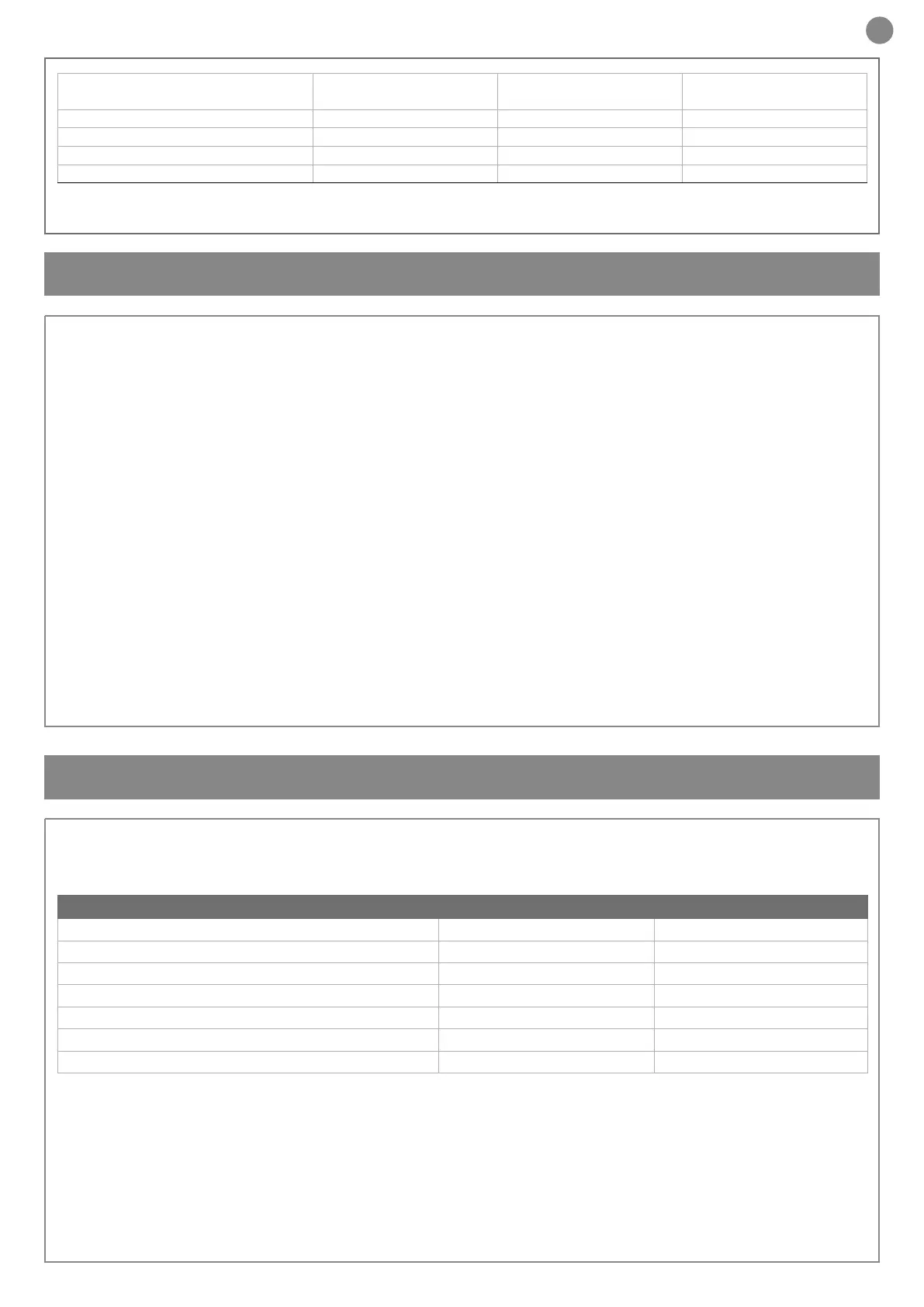
* If the power supply cable is more than 20 m long, it must be of larger gauge (3x2.5mm2) and a safety grounding system must be installed
near the automation unit.
ELECTRIC CABLE TECHNICAL SPECIFICATIONS:
Connection cable maximum allowable limit
Control unit power supply line 1 x cable 3 x 1,5 mm
2
20 m *
Antenna 1 x cable type RG58 20 m (advised < 5 m)
Transmitter photocells 1 x cable 2 x 0,5 mm
2
20 m
Receiver photocells 1 x cable 4 x 0,5 mm
2
20 m
Sensitive edge 1 x cable 2 x 0,5 mm
2
20 m
Key-switch 1 x cable 4 x 0,5 mm
2
** 20 m
Use in a particularly acid / saline /
explosive atmosphere
No No No
Dimensions (L-P-H) 450-280-1188 mm 360-220-1110 mm 450-280-1188 mm
Weight 62 Kg 47 Kg 67 Kg
Operating temperature -20°C + 55°C -20°C + 55°C -20°C + 55°C
Maximum length of rod 3 m 4 m 6 (8 mt)
* with 8 m bar
(1) with two xed red led discs
 Loading...