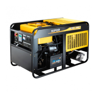
IG2000/IG2000s
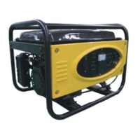
IG2000p
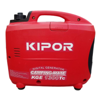
CG2000/CG2000s
6.2 Inspection
a. Control panel
● AC receptacle
Check the electrode contact disk inside receptacle, if it is burnt or the color changes, replace for it.
● DC receptacle
Connect both terminals of the receptacle with a jumper wire to short. There must be continuity between
the lead wire terminals with the circuit protector ON. Replace the DC receptacle if there is no continuity.
● Smart switch/LOAD SELECT Switch (CG series)
There should be continuity with the switch ON, and no continuity with the switch OFF.
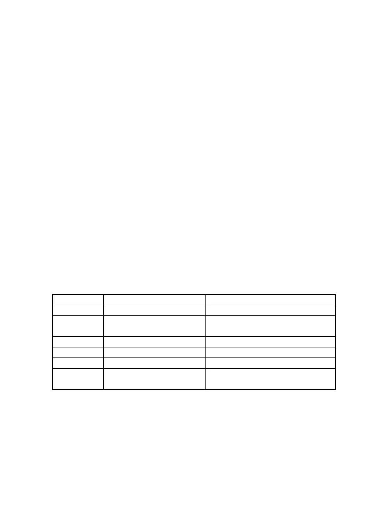
● Ignitor
Pull off the 10P receptacle from ignitor, measure the resistance by connecting one testing pen with the
metal outer case of engine, and the other testing pen with the 10P connector.
Color Circuit unit Standard resistance
Blue Primary coil of the ignition coil 0.8-1.3Ω
Orange Oil level alarm
There should be no continuity with correct
oil level
Yellow Trigger coil 80-130Ω
Yellow/Green Ground wire Continuity
Green Ignitor unit power coil winding 0.26-0.28Ω
Red Engine switch
There should be no continuity with the
switch ON, continuity with the switch OFF
35
 Loading...