27
WARNING: This saw was adjusted for accuracy at the factory. During shipping the components
may have been moved out of alignment. In addition, usage and time will necessitate
adjustments to be made.
To prevent personal injury:
● Always disconnect plug from the power source when making any adjustments.
● This adjustment must be correct or accurate cuts can not be made. Also inaccurate adjustment
can result serious personal injury.
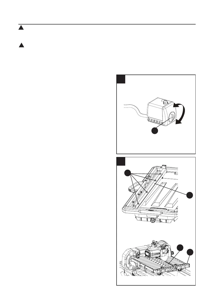
TO CONTROL THE FLOW OF WATER (FIG. 21)
● Fill the water tray with clean water as
described below.
● Locate the “Max/Min” water ow selector (1)
on the pump. For best performance, set the
ow to “Max” to control the ow of water over
the wheel.
● The pump turns on when the motor is turned
on. Let the cutting wheel build up to full speed
and wait for the wheel to get wet before moving
the tile into the wheel.
NOTE: The ow of water can also be adjusted
using the external water volume control. See
page 31 for instructions.
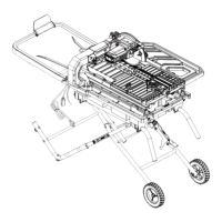
TO SQUARE THE CUTTING WHEEL TO THE
TABLE (FIG. 22)
Do not loosen any screws for this adjustment
until you have checked with a square and made
test cuts to be sure adjustments are necessary.
Once the screws are loosened, these items must
be reset.
● Disconnect the saw from the power source.
● Using the provided 5 mm hex key (RR),
loosen the four cap bolts (1) on the left rail (2).
● Place a framing square (3) against the sliding
T-fence extension (V) and the at part of the
wheel.
● Move the rail (2) until the sliding T-fence
extension (V) is square with the cutting wheel.
● Tighten the cap bolts (1) securely.
NOTE: Make sure the table stop is still
functional in the unlocked position so that
the sliding table does not slide o of the
table rails.
21
Max
Min
1
ADJUSTMENT INSTRUCTIONS
!
22
1
2
WARNING
!
3
V
 Loading...