6.9.2 Remote Start Connection
(optional)
Connect leads 3 and 4 from the ADC 2100 controller to
the automatic transfer switch's engine start terminals or
to an optional remote start!stop switch.
6.9.3 Continuous Power Mode Jumper
A jumper on connector P7 on the back of the controller
causes the controller to remain powered at all times.
See the wiring diagram and schematic drawing in
Section 5. Controllers are shipped from the factory with
the jumper connected. Disconnecting the jumper allows
the controller to power down 48 hours after the
generator set shuts down. See Section 2.3.6.
Note: For most applications, it is not necessary to
disconnect the continuous power mode jumper.
Use the following procedure to disconnect the jumper, if
desired.
Procedure to disconnect the continuous power
mode jumper (optional).
1. Prevent the generator set from starting.
a. Move the generator set master switch to the
OFF/RESET position.
b. Disconnect power to the battery charger.
c. Disconnect the generator set engine starting
battery, negative (-) lead first.
2. Remove the controller from the generator set
housing.
a. Disconnect the engine wiring harness
connector P1 plug (35-pin) from the controller.
Disconnect the J15 and J16 connectors. See
Figure 6-14.
b. Remove the controller from the generator set
housing in order to access the back of the
controller.
3. Remove the controller's back cover to access the
jumper.
a. Note the labels on the three leads connected to
the generator set master switch for
reconnection later. Disconnect the leads at the
pink connectors. See Figure 6-14.
b. Remove the cover screws and remove the
controller's back cover. See Figure 6-14.
4.
5.
6.
7.
8.
9.
10.
Locate the P7 connector near the top of the
controller. See Figure 6-14. Remove the jumper
from pins 1 and 2 of the P7 connector. If the P7
connector has three pins, connect the jumper
across pins 2 and 3 for storage.
Replace the controller's back cover and secure the
cover screws.
Reconnect the three pink connectors to the
generator set master switch.
Reconnect the J 15 and J 16 connectors.
Reconnect the generator set engine starting
battery, negative (-) lead last.
Reconnect power to the battery charger.
Place the generator set master switch in the AUTO
position.
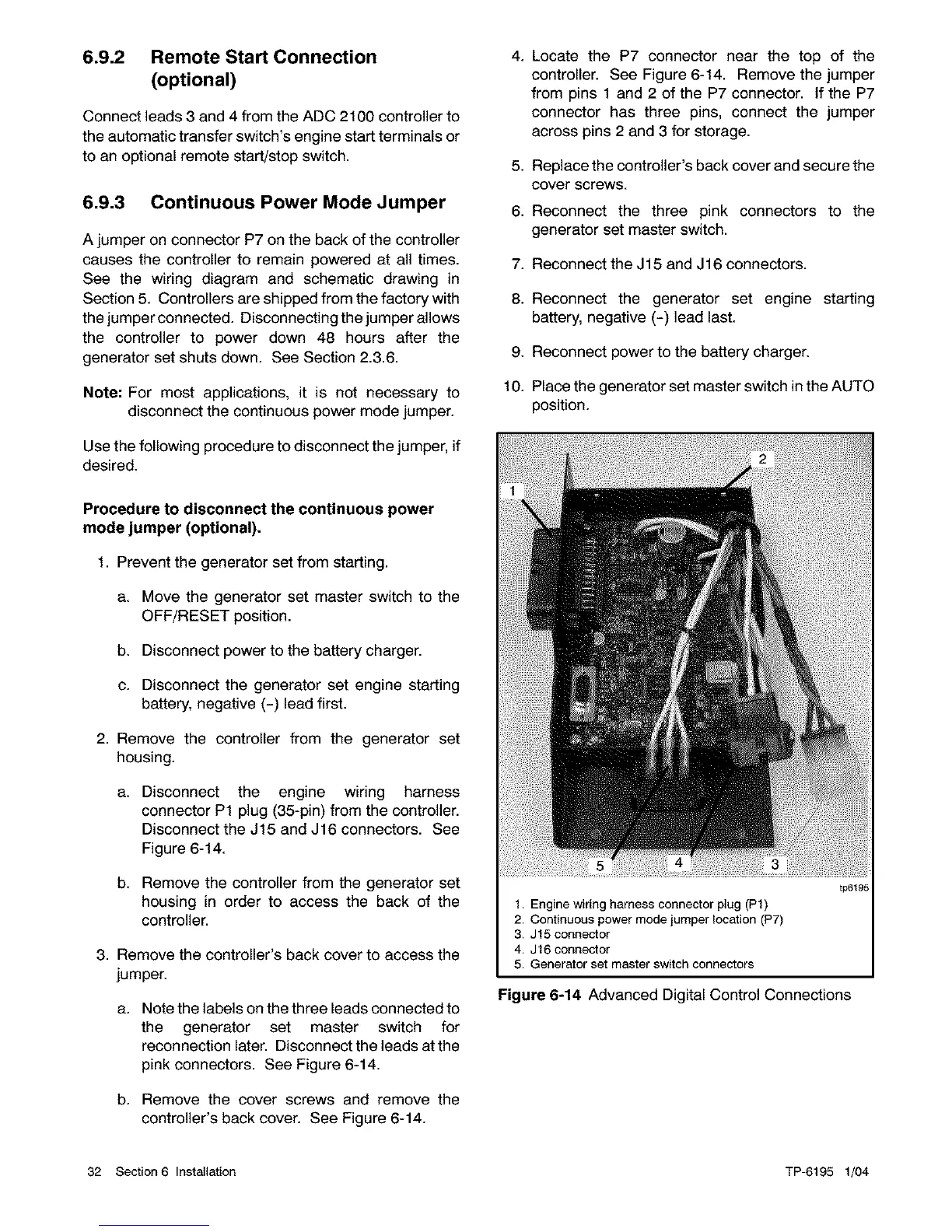
1. Engine wiring harness connector plug (P1)
2. Continuous power mode jumper location (P7)
3, J15 connector
4, J16 connector
5, Generator set master switch connectors
tp6195
Figure 6-14 Advanced Digital Control Connections
32 Section6 Installation TP-6195 1/04

 Loading...


