TP-6517 4/0930 Section 3 Scheduled Maintenance, 12 kW Models
Clean the battery and cables and tighten battery
terminals using the service schedule recommendations.
To prevent corrosion, maintain tight, dry electrical
connections at the battery terminals. To remove
corrosion from battery terminals, disconnect the cables
from the battery and scrub the terminals with a wire
brush. Clean the battery and cables with a solution of
baking soda and water. After cleaning, flush the battery
and cables with clean water and wipe them with a dry,
lint-free cloth.
After reconnecting the battery cables, coat the battery
terminals with petroleum jelly, silicone grease, or other
nonconductive grease.
3.9 Battery Charger
The generator set is equipped with a 6-amp
float/equalize battery charger to maintain the engine
starting battery. The charger’s DC leads are factory-
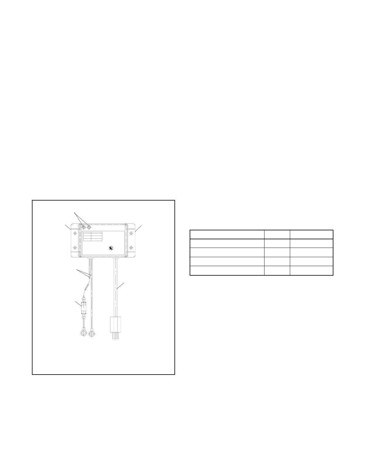
wired. Figure 3-9 illustrates the battery charger.
Periodically tighten all connections. No other
maintenance on the battery charger is required.
INDICATOR
Red:
Red & Green:
Green:
VOLTS= 11.8--14.0
AMPS= 5.0--6.0
VOLTS= 14.0--14.5
AMPS= 1.5--5.0
VOLTS= 13.0--13.6
AMPS= 0.1--1.5
CAUTION:To reduce the r isk of elect rical shock,
connect only to properly gr ounded outlet.
Allowable Battery Types: Lead Acid a nd Gel Cell
INPUT: 115 VAC 50/60Hz @ 1.6A
OUTPUT: 12 VDC @ 6 Amps
MAX. BAT.: 180 Amp Hr. Max.
DATE:
6 AMP AUTOMATIC
BATTERY CHARGER
R
C US LISTED
BATTERY C HARGER
53AB
2608KH
1
1. LED indicators
2. Mounting flanges
3. AC power cord
2
5
2
3
4
4. Fuse
5. Battery leads, 12 VDC
Figure 3-9 6-Amp F loat/Equalize Battery Charger
3.10 Circuit Protection
If the generator set circuit breaker trips or the fuses blow
repeatedly, see Section 5, Troubleshooting, for possible
causes.
3.10.1 Line Circuit Breaker
A line circuit breaker interrupts the generator output in
the event of a fault in the wiring between the generator
and the load. The line circuit breaker location is shown
in Figure 1-1. The circuit breaker rating is 50 amps. If
the circuit breaker trips, reduce the load and switch the
breaker back to the ON position. With the breaker in the
OFF position, the generator set runs but the generator
output is disconnected from the load.
3.10.2 Fuses
Two 10-amp and one 20-amp inline fuse are mounted
on the controller junction box. See Figure 3-10. Another
10-amp fuse is located in the battery charger lead.
Always identify and correct the cause of a blown fuse
before restarting the generator set. Refer to Section 5,
Troubleshooting, for conditions that may indicate a
blown fuse. Replace blown fuses with identical
replacement parts.
Fuse Label Part Number
Auxiliary winding, 20 A F1 292937
Relay interface board, 10 A F2 223316
Controller, 10 A F3 223316
Battery charger, 10 A — 223316
Figure 3-10 Fuses
 Loading...


