TP-6109 6/03 17Section 2 Operation
2.8 Standard Decision-Makert 1
Controller Operation
For identification of the standard basic controller’s
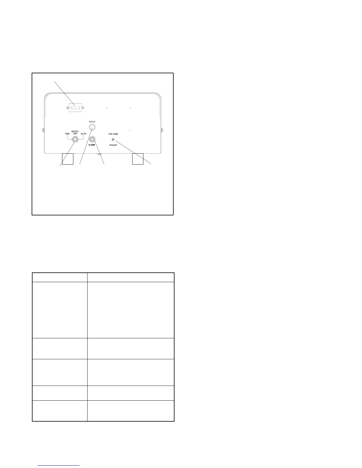
indicators and controls and their functions, refer to
Figure 2-5.
A-227600
1
345
1. Hourmeter
2. Voltage adjustment
3. 10-amp controller fuse
4. Fault lamp
5. Generator set master switch
2
Figure 2-5 Decision-Maker t 1 Controller
x:op:004:001
2.8.1 Controls and Indicators
The following table describes the controls and indicators
located on the controller.
Name Description
Fault lamp Lamp illuminates during engine
shutdown if the engine shuts down
because of one of the following
faults: high engine temperature,
low water level, low oil pressure,
overcrank, or overspeed. See
Section 2.8.4, Fault Shutdowns,
for additional shutdown
information.
Generator set master
switch
Switch functions as the controller
reset and generator operation
switch.
Hourmeter Hourmeter records the generator
set total operating hours for
reference in maintenance
scheduling.
Voltage adjust
potentiometer
Potentiometer fine-tunes (±5%)
generator output voltage.
10-amp controller
fuse
Fuse protects the controller
circuitry from short circuits and
overloads.
x:op:004:002
2.8.2 Starting the Generator Set
The following procedures describe starting the
generator set.
Local Starting. Move the generator set master switch
to the RUN position to immediately start the generator
set.
Automatic (Auto) Starting. Move the generator set
master switch to the AUTO position to allow startup by
the automatic transfer switch or the remote start/stop
switch (connected to controller terminals TB1-3 and
TB1-4).
Note: The controller provides up to 30 seconds of
continuous cranking before the overcrank
shutdown occurs.
2.8.3 Stopping the Generator Set
The following procedure describe how to stop the
generator set.
Normal Stopping
1. Cooldown. Run the generator set at no load for
5 minutes to ensure adequate engine cooldown.
2. Stopping. Move the generator set master switch
to the OFF/RESET position. The engine stops.
x:op:004:004
 Loading...
