TP-6391 9/0814 Section 1 Specifications
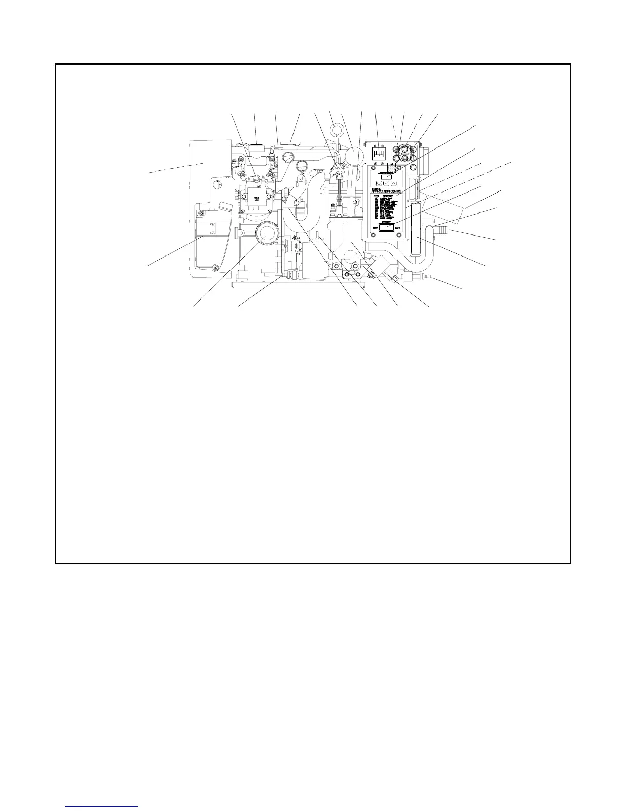
1.8 Service View
25
15
2
21
29 28
23
26
30
4
31
10 11
12
19
18
13
9
22
27
87
SERVICE VIEW
1 3
20
1. Spark plug (also one located on the nonservice side)
2. Oil fill
3. Overflow tube
4. Pressure cap (coolant fill location after draining coolant)
5. Seawater pressure switch (appears as auxiliary fault on ADC)
6. Lifting eye
7. Heat exchanger
8. Anticorrosion zinc anode
9. AC circuit breaker
10. AC load lead connector (nonservice side)
11. Nameplate (top)
12. Remote start connector (nonservice side)
13. Fuses (F1, F2, F3, F4, F5, F6, and F7)
14. Runtime hour display
15. ADC 2100
16. High exhaust temperature switch (located on the catalyst on
the nonservice side). Available on units with serial numbers
2199434 and later. (Appears as LOC fault on ADC.)
17. CO sensor module (available on units with serial number
2085259 and later)
18. Generator set master switch
19. Catalyst assembly, water outlet/exhaust outlet (nonservice
side)
20. Seawater drain (remove plate for service)
21. Seawater pump (water inlet)
22. Cooling air inlet
23. Fuel filter/fuel inlet
24. Fuel pump
25. Fuel pump/cooler
26. Oil check
27. Coolant drain (remove hose clamp to drain coolant)
28. Oil drain valve
29. Lube oil filter
30. Coolant overflow bottle (daily coolant check/fill location)
31. Air intake silencer/backfire flame arrestor
Note: Consult installation drawings in Spec Sheet or Installation
Manual for fuel- and battery-connection points.
5
14
24
6
ADV7025A-A
17
16
Figure 1-2 Service Views
 Loading...
