TP-6591 10/1322 Section 2 Operation
2.6.5 Resetting the Controller after a
Fault Shutdown
Note: A fault is identified by a red b linking light in the
LED status indicator.
Always identify and correct the cause of a fault
shutdown before resetting the controller. Use the
following procedure to reset the generator set controller
after a fault shutdown.
1. Disconnect the generator set engine starting
battery(ies), negative (--) lead first.
2. Disconnect the generator set from the load. See
the safety precautions at the beginning of this
manual before proceeding.
3. Identify and correct the cause of the fault
shutdown. See the safety precautions at the
beginning of this manual before proceeding. Refer
to Section 4, Troubleshooting.
4. Reconnect the generator set to the load.
5. Reconnect the generator set engine starting
battery, negative (--) lead last.
6. Push the Advanced Digital Control knob.
7. Rotate the control knob to CONFIRM CLR FAULT:
YES
8. Push the control knob.
9. Start the generator set by pressing the generator
set start/stop button to START. Test operate the
generator set to verify that the cause of the
shutdown has been corrected.
10. Shut the generator off by pressing the generator
set start/stop to the STOP position.
2.6.6 USB Connection
The Advanced Digital Control II includes a USB
connection for updating software and configuring
parameters. See Figure 1-1 for location.
Note: Have software downloads, setup, and
adjustments of the Advanced Digital Control
performed only by an authorized Kohler
distributor/dealer.
2.7 Circuit Protection
If the generator set circuit breaker trips or the fuses blow
repeatedly, see Section 4 for possible causes.
2.7.1 Line Circuit Breaker
A line circuit breaker interrupts the generator output in
the event of a fault in the wiring between the generator
and the load. The line circuit breaker location is shown
in Section 1. If the circuit breaker trips, reduce the load
and switch the breaker back to the ON position.
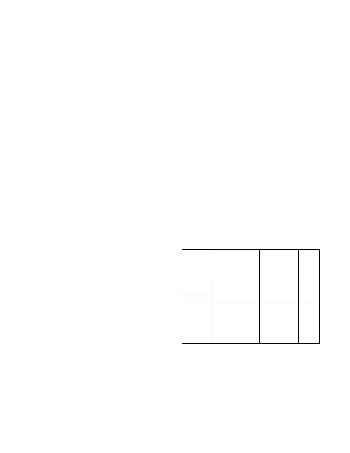
2.7.2 Fuses
The junction box contains five fuses. See Figure 1-1 for
the fuse locations. Always identify and correct the cause
of a blown fuse before restarting the generator set.
Refer to section 4 for conditions that may indicate a
blown fuse. Obtain service from an authorized
distributor/dealer.
Schematic
Diagram
Fuse
Reference
Number
Location Fuse Amps
F1 Fuse block position 1 Customer
connection
10
F2 Fuse block position 4 Voltage regulator 25
F3 Fuse block position 5 Injector,
CO sensor,
fuel pumps,
oxygen sensor,
and coils
20
F4 Fuse block position 8 Controller 10
F5 Fuse holder Auxiliary winding 10
Figure 2-9 Fuses
 Loading...