TP-6195 1/04 13Section 3 Scheduled Maintenance
1. Place the generator set master switch in the
OFF/RESET position.
2. Disconnect the power to the battery charger.
3. Disconnect the generator set engine starting
battery, negative (--) lead first.
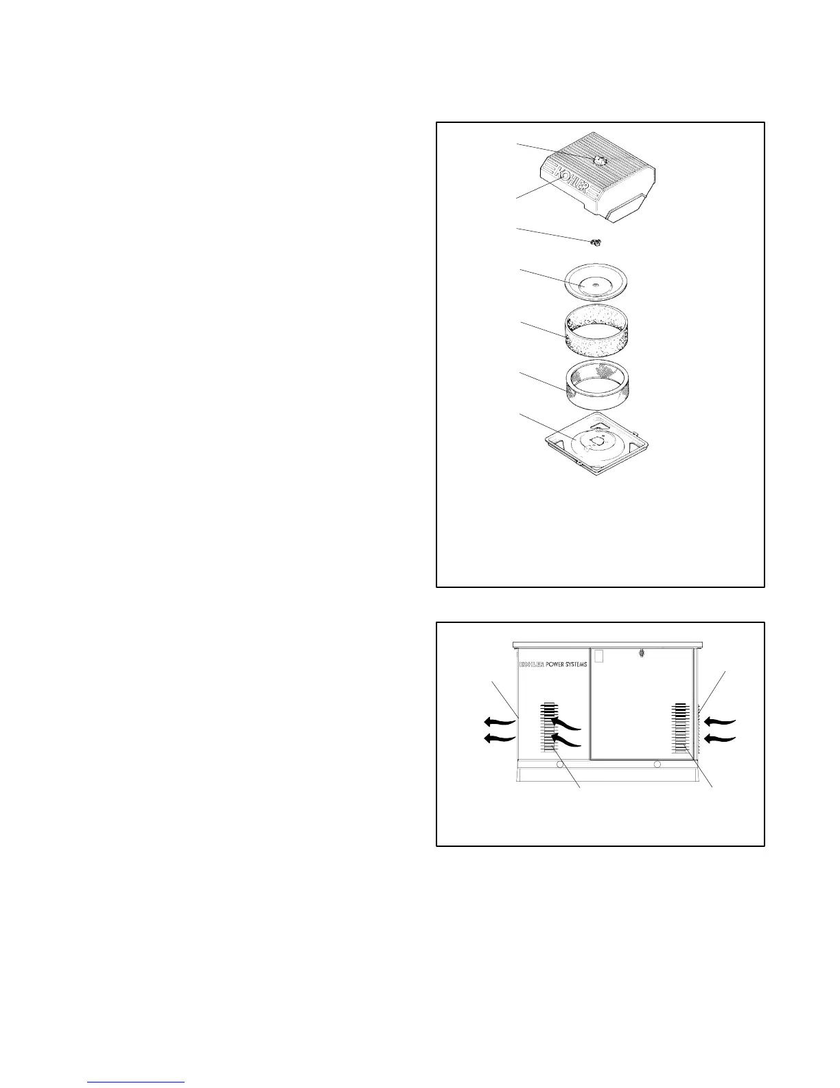
4. Loosen the cover retaining knob and remove the
cover.
5. Remove the element cover nut, element cover, and
the paper element with precleaner.
6. Remove the precleaner from the paper element.
Note: Do not wash the paper element or clean it
with pressurized air, as this will damage the
element.
7. Replace the element if it is dirty, bent, or damaged.
8. Check the air cleaner base. Make sure it is secure
and not bent or damaged. Also check the element
cover for damage and fit. Replace all damaged air
cleaner components. Remove any loose dirt or
debris from the air cleaner base. Wipe the base
carefully so that no dirt drops into the intake throat.
Check the condition of the rubber seal on the air
cleaner stud and replace the seal if necessary.
9. Reinstall the paper element, precleaner, element
cover, element cover nut, and the air cleaner cover.
Secure the cover with the cover retaining knob.
10. Reconnect the power to the battery charger.
11. Reconnect the generator set engine starting
battery, negative (--) lead last.
3.6 Cooling S ystem
The engine fan draws cooling air through the openings
in the sides and end near the battery. The alternator fan
draws cooling air through openings on the side walls of
the enclosure. The cooling air mixes with the engine
exhaust and is discharged at the exhaust outlet. See
Figure 3-6. To prevent generator set damage caused by
overheating, keep the housing cooling inlets and outlets
clean and unobstructed at all times.
Note: Do not block the generator set cooling air inlets or
mount other equipment above them.
Overheating and severe generator damage may
occur.
1
2
3
4
5
6
7
586536
1. Cover knob
2. Air cleaner cover
3. Element cover nut
4. Element cover
5. Foam precleaner
6. Air cleaner element
7. Air cleaner base
Figure 3-5 Air Cleaner Components
tp6195
2
1. Exhaust outlet
2. Alternator air intake (both sides)
3. Engine air intake
3
1
3
Figure 3-6 Cooling Air Intake and Exhaust
 Loading...