TP-6195 1/04 31Section 6 Installation
6.9 Electrical Connections
6.9.1 AC Load Lead Connections
Hazardous voltage.
Backfeed to the utility system can
cause property damage, severe
injury, or death.
If the generator set is used for
standby power, install an automatic
transfer switch to prevent inadvertent
interconnection of standby and
normal sources of supply.
WARNING
Grounding electrical equipment. Hazardous voltage can
cause severe injury or death. Electrocution is possible
whenever electricity is present. Open the main circuit
breakers of all power sources before servicing the equipment.
Configure the installation to electrically ground the generator
set, transfer switch, and related equipment and electrical
circuits to comply with applicable codes and standards. Never
contact electrical leads or appliances when standing in water
or on wet ground because these conditions increase t he risk of
electrocution.
Electrical backfeed to the utility. Hazardous backfeed
voltage can cause severe injury or death. Install a transfer
switch in standby power installations to prevent the connection
of standby and other sources of power. Electrical backfeed
into a utility electrical system can cause severe injury or death
to utility personnel working on power lines.
NOTICE
Canadian installations only. For standby service connect
the output of the generator set to a suitably rated transfer
switch in accordance with Canadian Electrical Code, Part 1.
Have an authorized distributor/dealer or a licensed
electrician make the following load connections. Verify
that the electrical installation complies with the National
Electrical Code (NEC) and all applicable local and state
codes.
Connect the AC output leads in the controller
compartment to the AC circuit breaker. Route AC leads
through flexible conduit directly to the AC circuit breaker
box. See Figure 6-1 for the recommended electrical
inlet location. Verify that the leads and conduit do not
interfere with the operation of the generator set or
obstruct the service areas.
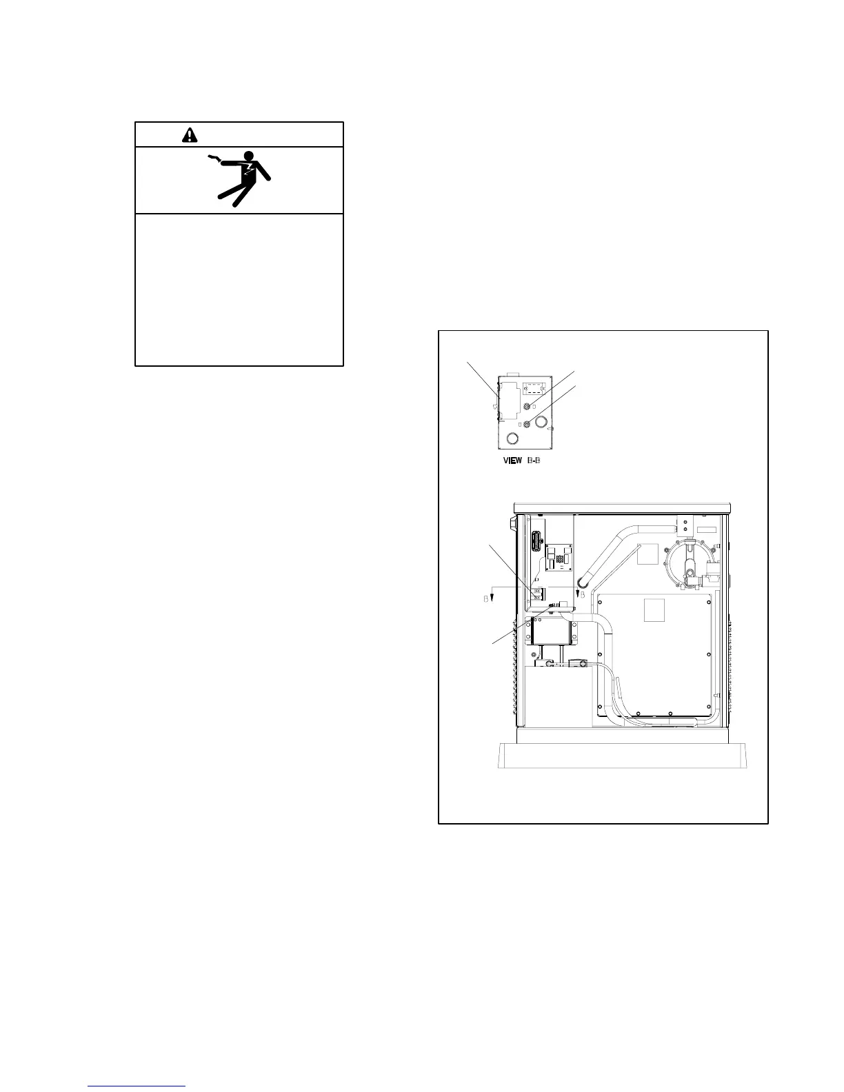
See Figure 6-13 and Section 5, Wiring Diagrams, for
the generator set electrical connections. Make the
following AC connections:
1. Connect the output leads going to the transfer
switch (L1/L2 black leads) to the AC circuit breaker
load side.
2. Connect the L0 white leads from the ATS and the
main panel to the neutral terminal.
3. Connect the green lead to the equipment ground
terminal (labeled GRD).
Verify that the electrical installation complies with the
National Electrical Code (NEC) and all applicable local
and state codes.
2,
1
GM29253A-F
1. Line circuit breaker
2. Ground terminal (GRD)
3. Neutral terminal (L0)
1
2
3
3
Bottom of J unction Box
Figure 6-13 Field-Installed Wiring Connections
 Loading...