11.13
Section 11
Reassembly
11
Figure 11-42. Installing Cylinder Head Baffle and
Intake Tube.
Figure 11-41. Installing Cylinder (Intake Side) Baffle.
NOTE: Leave all hardware slightly loose until all
sheet metal pieces are in position.
3. Install the cylinder head baffle to the cylinder head
using the hex flange screws. Torque the screws to
3.9 N·m (35 in. lb.). See Figure 11-42.
4. Tighten all other mounting hardware securely.
5. Reinstall the intake tube to the opening in the
blower housing.
Install Valve Cover and Muffler Bracket
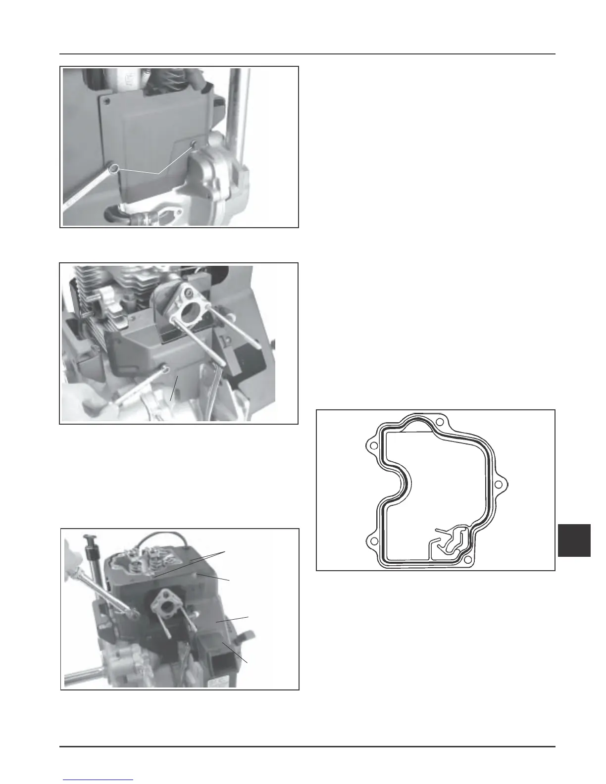
RTV silicone sealant is used as a gasket between the
valve cover and crankcase. Refer to page 2.3 for a
listing of approved sealants.
NOTE: Always use fresh sealant. Using outdated
sealant can result in leakage. Refer to Section
2 Tools & Aids for information on the sealant
dispenser.
1. Prepare the sealing surfaces of the cylinder head
and valve cover following Service Bulletin 252. If
it is a stamped steel valve cover, the flatness of
the sealing surface must be checked prior to
reinstallation. See Section 10.
2. Apply a 1/16" bead of sealant to the cylinder head
as shown in Figure 11-43.
NOTE: To ensure proper adhesion of the sealant
to both sealing surfaces, perform Step 3
immediately (5 minutes maximum) after
application of RTV.
Figure 11-43. Valve Cover Sealant Pattern.
Cylinder (Intake Side) Baffle
Cylinder
Head Baffle
Blower
Housing
Hex Flange
Screws
Intake
Tube
Figure 11-40. Installing Cylinder (Starter Side)
Baffle.
Hex Flange
Screws
Cylinder (Starter Side)
Baffle
Blower
Housing
 Loading...


