11.15
Section 11
Reassembly
11
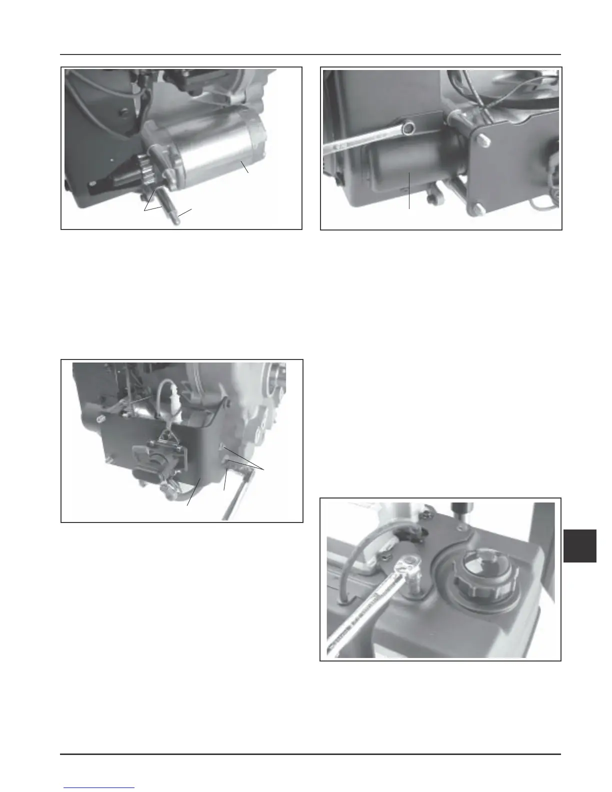
Figure 11-49. Installing Starter Cover.
4. Install the starter cover and secure with the two
hex flange screws. See Figure 11-49.
5. Connect the lead(s) to the starter or solenoid
terminals. To avoid damage or breakage, do not
overtighten the hex flange nut. Torque the nut to
6-9 N·m (53-79 in. lb.).
Install Fuel Tank
1. Connect the fuel hose to the shut-off valve.
2. Install hex flange screws through upper bracket
into fuel tank. Install hex flange nuts onto studs
to secure the lower fuel tank mounting bracket.
Torque the screws to 7.3 N·m (65 in. lb.). See
Figure 11-50.
3. Torque the hex flange nuts to 24.4 N·m
(216 in. lb.). See Figure 51.
Figure 11-47. Installing Electric Starter.
3. Install fuel tank/solenoid bracket (if equipped)
onto the mounting studs. Secure with the two hex
flange screws through the closure plate, with the
single spacer behind the bracket on the lower
screw. Torque the screws to 24.4 N·m
(216 in. lb.). See Figure 11-48. If the bracket is
being installed with the closure plate, refer to
Figure 11-20 for proper torque sequence.
Figure 11-48. Installing Fuel Tank/Solenoid Bracket
(some models).
Figure 11-50. Installing Fuel Tank Upper Mounting
Screws.
Starter
Spacers
Studs with Spacers/or
Mounting Bolts
Bracket
Spacer
Hex
Flange
Screws
Starter Cover
 Loading...


