4324 690 07 Rev. H KohlerEngines.com
Electrical System
Test Ignition Modules and Connections (Smart-
Spark
™
only)
NOTE: Resistance values apply only to modules that
have been on a running engine. New service
modules may have higher resistance until they
have been run.
1. Remove blower housing from engine. Inspect wiring
for any damage, cuts, bad crimps, loose terminals,
or broken wires.
2. Disconnect leads from ignition module(s) and clean
all of terminals (male and female) with aerosol
electrical contact cleaner to remove any old
dielectric compound, dark residue, dirt, or
contamination. Disconnect spark plug leads from
spark plugs.
3. Remove one mounting screw from each ignition
module. If mounting screws are black, remove them
both and discard. Look in mounting hole with a
ashlight and use a small round wire brush to
remove any loose rust from laminations inside
mounting hole.
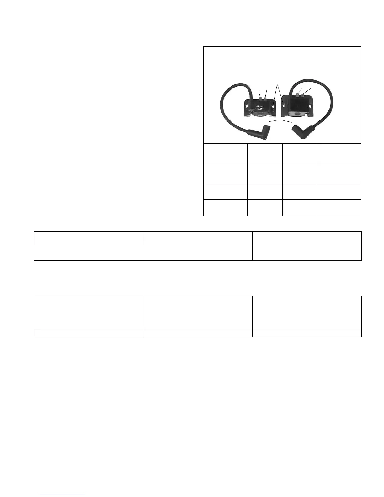
4. Use a digital ohmmeter to check resistance values
and compare them to ignition module resistance
table. When testing resistance to laminations, touch
probe to laminations inside screw hole, as some
laminations have a rust preventative coating on
surface which could alter resistance reading.
Condition Possible Cause Conclusion
All resistance values are within
ranges specied in table.
Ignition Module Gap Check and adjust ignition module
gap.
At least 1 resistance value is not
within ranges specied in table.
Ignition Module Ignition module is faulty and should
be replaced.
2
1
4
2
1
3
24 584 03
or
24 584 11
(1 11/16 in. High)
24 584 15-S
or
24 584 36-S
(2 1/16 in. High)
Test
(Use Digital
Ohmmeter)
From No.
1 to 4
From No.
2 to 4
From No.
3 to 4
24 584 03
24 584 11
(1 11/16 in. H)
945 to
1175 ohms
149 to
166 ohms
3750 to
7000 ohms
24 584 15-S
(2 1/16 in. H)
890 to
1175 ohms
119 to
136 ohms
5600 to
9000 ohms
24 584 36-S
(2 1/16 in. H)
590 to
616 ohms
183 to
208 ohms
8000 to
40,000 ohms
Ignition Module Resistance Table
5. Check and/or adjust ignition module air gap(s). An air gap of 0.28/0.33 mm (0.011/0.013 in.) must be maintained
under all three legs of ignition module(s). Checking/adjusting should be performed with parts at room temperature.
Condition Possible Cause Conclusion
Module was not loosened or
replaced.
Ignition Module Air Gap Check that specied air gap is
present under all three legs. If gap is
correct, reinstall second mounting
screw removed earlier and recheck
gap after tightening.
Module was loosened or replaced. Ignition Module Adjust ignition module air gap.
a. Adjust ignition module air gap.
1. Turn ywheel magnet away from module position.
2. Attach module to mounting legs, pull it away from ywheel, and tighten screws to hold it temporarily.
3. Rotate ywheel so magnet is centered under module.
4. Position a 0.30 mm (0.012 in.) feeler gauge between magnet and all three legs of module. Ignition module
air gap is critical to proper system performance. Do not attempt to set it with a business card or folded
microche card. Use feeler gauge specied.
5. Loosen mounting screws, allow magnet to pull module down against feeler gauge, and retighten mounting
screws.
6. Rotate ywheel to remove feeler gauge, position magnet back under module, and recheck that specied
gap, minimum of 0.28 mm (0.011 in.), exists under each leg of module. When you are certain gap is correct,
torque module mounting screws to 4.0 N·m (35 in. lb.). Repeat these 6 steps to set other ignition module.
6. Reattach lead wires to ignition module(s), noting if resistance is felt, indicating a snug t between male and female
terminals. If any connections do not feel snug, disconnect lead, lightly pinch female terminal with a pliers, and
recheck t.
7. When integrity of all connections has been veried, retest for spark.
 Loading...