Electrical System
46 24 690 07 Rev. HKohlerEngines.com
15/20/25 Amp Regulated Charging System
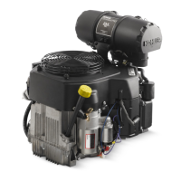
Stator
Stator is mounted on crankcase behind ywheel. Follow procedures in Disassembly and Reassembly if stator
replacement is necessary.
Rectier-Regulator
NOTE: When installing rectier-regulator, take note of terminal markings and install plug(s) accordingly.
NOTE: Disconnect all electrical connections attached to rectier-regulator. Testing may be performed with rectier-
regulator mounted or loose. Repeat applicable test procedure 2 or 3 times to determine condition of part.
Rectier-regulator is mounted on blower housing. To replace it, disconnect plug(s), remove mounting screws, and
ground wire or metal grounding strap.
Testing of rectier-regulator may be performed as follows, using appropriate Rectier-Regulator Tester.
To test 4/15 amp rectier-regulators:
1. Connect tester ground lead (with spring clamp) to
body of rectier-regulator being tested.
2. Connect tester red lead to B+ terminal of rectier-
regulator and 2 black tester leads to 2 AC terminals.
3. Plug tester into proper AC outlet/power for tester
being used. Turn on power switch. POWER light
should be illuminated and 1 of 4 status lights may be
on as well. This does not represent condition of part.
4. 4 amp: Press TEST button until a click is heard and
then release. Momentarily either HIGH, LOW, or
SHORT light will ash.
15 amp: Press TEST button until a click is heard and
then release. Momentarily 1 of 4 status lights will
illuminate, indicating condition of part.
To test 20/25 amp rectier-regulators:
1. 20 amp: Connect single lead adapter in between B+
(center) terminal of rectier-regulator being tested
and squared single end of tandem adapter lead.
25 amp: Connect squared single end of tandem lead
adapter to B+ (center/red) lead of rectier-regulator
being tested.
2. Connect tester ground lead (with spring clamp) to
body of rectier-regulator.
3. Connect red lead and 1 black lead to pair of
terminals on open end of tandem adapter lead
(connections are not location specic).
4. Connect remaining black lead from tester to 1 outer
AC terminal on rectier-regulator.
5. Plug tester into proper AC outlet/power for tester
being used. Turn on power switch. POWER light
should be illuminated and 1 of 4 status lights may be
on as well. This does not represent condition of part.
6. Press TEST button until a click is heard and then
release. Momentarily 1 of 4 status lights will
illuminate indicating partial condition of part.
Condition Conclusion
4 amp 15 Amp 20 amp 25 amp
OK (green) or HIGH light comes on
and stays steady.
Part is good and may be used. Disconnect tester black lead attached
to 1 AC terminal and reconnect it to
other AC terminal. Repeat test. If OK
(green) light comes on again, part is
good and may be used.
NOTE: A ashing LOW light can
also occur as a result of an
inadequate ground lead
connection. Make certain
connection location is clean
and clamp is secure.
Other lights come on.
Rectier-regulator is faulty and should not be used.
 Loading...