64
Disassembly/Inspection and Service
KohlerEngines.com 24 690 06 Rev. K
1. Remove screws or nuts and washers securing each
cylinder head. Unless screws are damaged or
questionable, they can be reused. Discard nuts and
washers once removed; do not reuse. Studs (if
present) should only be removed if damaged or if
cylinder reconditioning is necessary. Once removed,
they must be replaced.
2. Mark position of push rods as either intake or
exhaust and cylinder 1 or 2. Push rods should
always be reinstalled in same positions.
3. Carefully remove push rods, cylinder heads and
head gaskets.
4. Remove lifters from lifter bores. Use a Hydraulic
Lifter Tool. Do not use a magnet to remove lifters.
Mark lifters by location, as either intake or exhaust
and cylinder 1 or 2. Hydraulic lifters should always
be reinstalled in same position.
Disassemble Cylinder Heads
NOTE: These engines use valve stem seals on intake
valves. Use a new seal whenever valve is
removed or if seal is deteriorated in any way.
Never reuse an old seal.
1. Remove screws, rocker arm pivots and rocker arms
from cylinder head.
2. Compress valve springs using a valve spring
compressor.
3. Once valve spring is compressed, remove following
items.
● Valve spring keepers.
● Valve spring retainers.
● Valve springs.
● Valve spring caps.
● Intake and exhaust valves (mark position).
● Valve stem seals (intake valve only).
4. Repeat above procedure for other cylinder head. Do
not interchange parts from one cylinder head to
other.
Inspection and Service
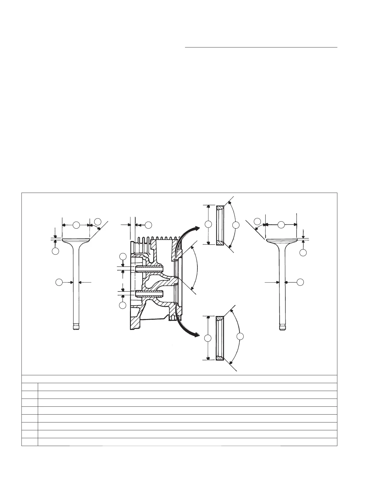
Valve Details
EXHAUST VALVE INTAKE VALVE
EXHAUST
INSERT
INTAKE
INSERT
H
H
G
G
E
E
F
F
A
A
C
D
D
B
B
Dimension Intake Exhaust
A Seat Angle 89° 89°
B Insert O.D. 36.987/37.013 mm (1.4562/1.4572 in.) 32.987/33.013 mm (1.2987/1.2997 in.)
C Guide Depth 4 mm (0.1575 in.) 6.5 mm (0.2559 in.)
D Guide I.D. 7.038/7.058 mm (0.2771/0.2779 in.) 7.038/7.058 mm (0.2771/0.2779 in.)
E Valve Head Diameter 33.37/33.63 mm (1.3138/1.3240 in.) 29.37/29.63 mm (1.1563/1.1665 in.)
F Valve Face Angle 45° 45°
G Valve Margin (Min.) 1.5 mm (0.0591 in.) 1.5 mm (0.0591 in.)
H Valve Stem Diameter 6.982/7.000 mm (0.2749/0.2756 in.) 6.970/6.988 mm (0.2744/0.2751 in.)
 Loading...