Governor System
3562 690 01 Rev. J KohlerEngines.com
This governor design works as follows:
● Centrifugal force acting on rotating governor gear
assembly causes yweights to move outward as
speed increases. Governor spring tension moves
them inward as speed decreases.
● As yweights move outward, they cause regulating pin
to move outward.
● Regulating pin contacts tab on cross shaft causing
shaft to rotate.
● One end of cross shaft protrudes through crankcase.
Rotating action of cross shaft is transmitted to throttle
lever of carburetor through external throttle linkage.
● When engine is at rest, and throttle is in fast position,
tension of governor spring holds throttle plate open.
When engine is operating, governor gear assembly is
rotating. Force applied by regulating pin against cross
shaft tends to close throttle plate. Governor spring
tension and force applied by regulating pin balance
each other during operation, to maintain engine
speed.
● When load is applied and engine speed and governor
gear speed decreases, governor spring tension moves
governor arm to open throttle plate wider. This allows
more fuel into engine, increasing engine speed. As
speed reaches governed setting, governor spring
tension and force applied by regulating pin will again
offset each other to hold a steady engine speed.
Governor Adjustments
NOTE: Do not tamper with governor setting. Overspeed
is hazardous and could cause personal injury.
Initial Adjustment Procedure
Make this adjustment whenever governor arm is
loosened or removed from cross shaft. Adjust as follows:
1. Make sure throttle linkage is connected to governor
arm and throttle lever on carburetor.
2. Loosen nut holding governor lever to cross shaft.
3. Move governor lever toward carburetor as far as it
will go (wide open throttle) and hold in this position.
4. Insert a long thin rod or tool into hole on cross shaft
and rotate shaft clockwise (viewed from end) as far
as it will turn, then torque nut to 7.1 N·m (63 in. lb.).
GOVERNOR
Governed speed setting is determined by position of throttle control. It can be variable or constant, depending on
engine application.
Governor is designed to hold engine speed constant under changing load conditions. Most engines are equipped with
a centrifugal yweight mechanical governor. Governor gear/yweight mechanism of mechanical governor is mounted
inside crankcase and is driven off gear on camshaft.
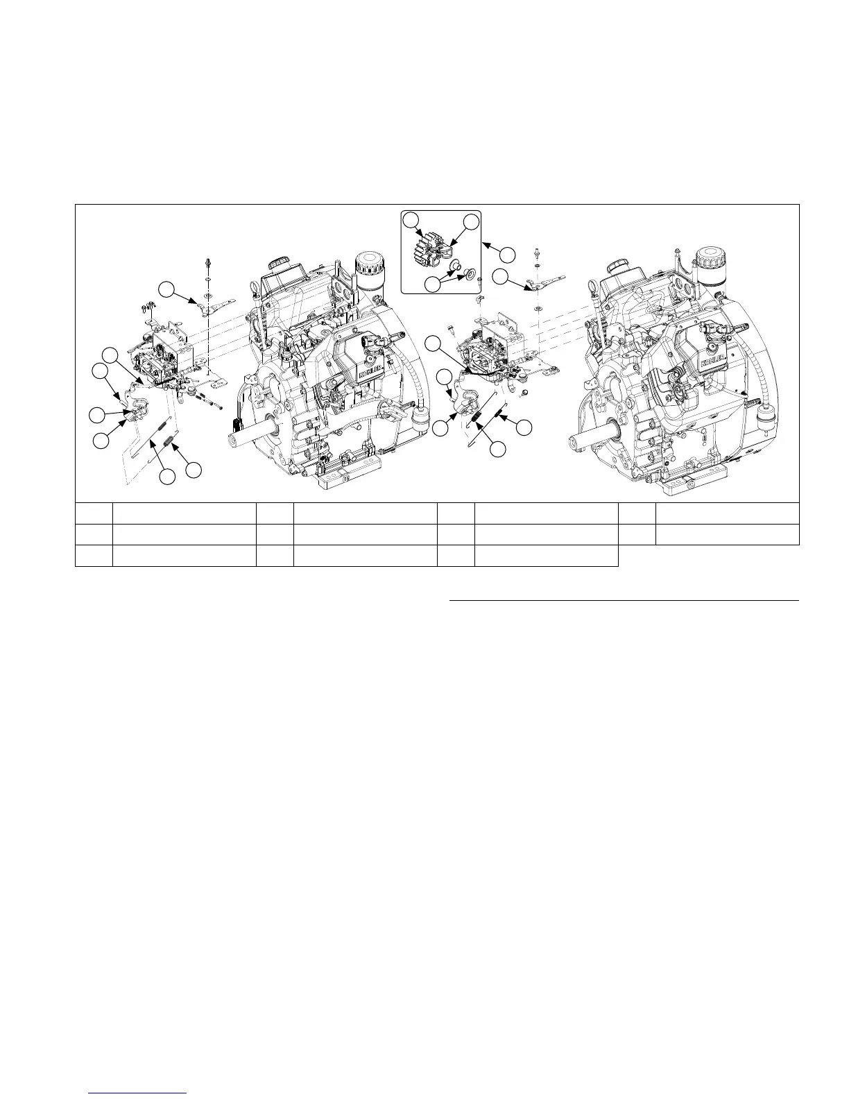
Governor Components
A
G
E
F
C
D
B
B
G
E
F
D
A
J
I
H
K
A Throttle Lever B Throttle Linkage C Nut D Governor Arm
E Governor Spring F Governed Idle Spring G Cross Shaft H Flyweight
I Regulating Pin J Governor Gear K Inside Engine
 Loading...