9.12
Section 9
Inspection and Reconditioning
Gear Shaft
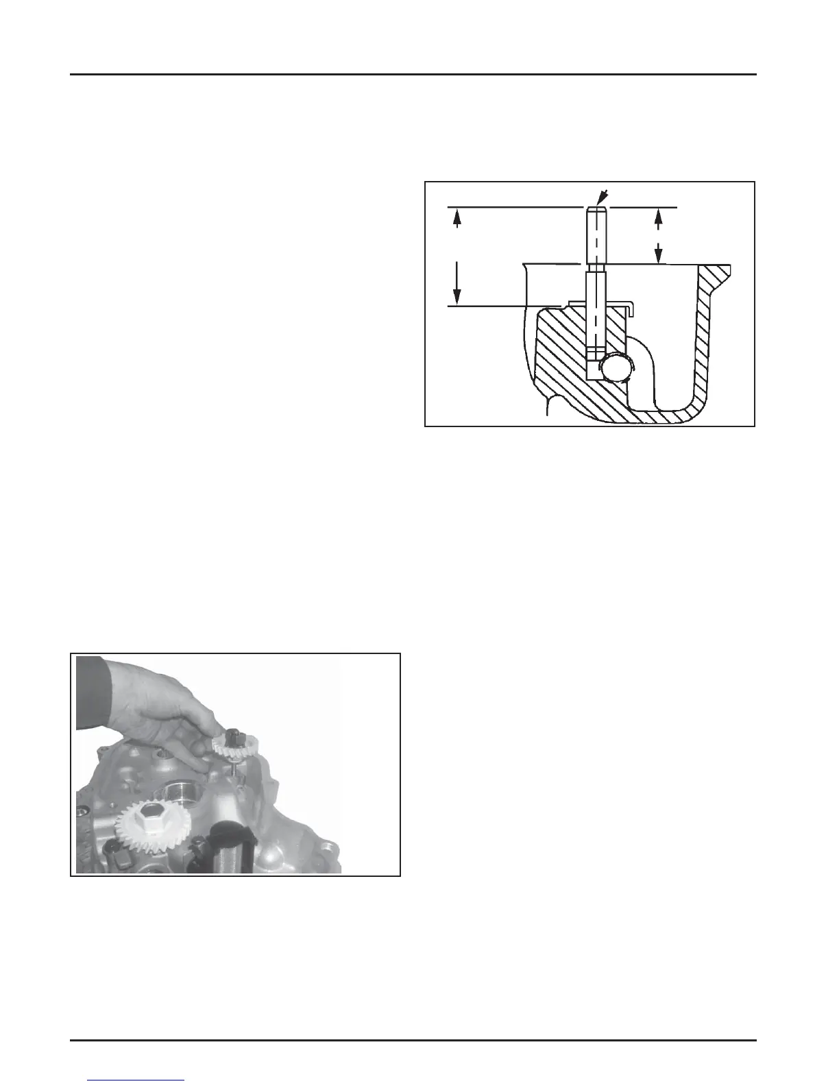
34.0 mm (1.3386 in.)
33.5 mm (1.3189 in.)
19.40 mm (0.7638 in.)
Closure Plate Assembly
Inspection
Inspect the oil seal in the closure plate and remove it if
it is worn or damaged. Refer to Install Closure Plate
Oil Seal in Section 10 for new oil seal installation.
Inspect the main bearing surface for wear or damage
(refer to Section 1, Specifi cations, Tolerances, and
Special Torque Values). Replace the closure plate
assembly if required.
Governor Gear Assembly
Inspection
Inspect the governor gear teeth. Replace the gear if it
is worn, chipped, or if any teeth are missing. Inspect
the governor weights. They should move freely in the
governor gear.
Disassembly
The governor gear must be replaced once it is
removed from the closure plate.
NOTE: The governor gear is held onto the sha by
small molded tabs in the gear. When the
gear is removed from the sha , these tabs
are destroyed and the gear must be replaced.
Therefore, remove the gear only if absolutely
necessary.
1. Remove the regulating pin and governor gear
assembly. See Figure 9-13.
Figure 9-13. Removing Governor Gear.
2. Remove the locking tab thrust washer located
under the governor gear assembly.
3. Carefully inspect the governor gear sha and
replace it only if it is damaged. A er removing
the damaged sha , press or lightly tap the
replacement sha into the closure plate to the
depth shown in Figure 9-14.
Figure 9-14. Governor Shaft Press Depth.
Reassembly
1. Install the locking tab thrust washer on the
governor gear sha with the tab down.
2. Position the regulating pin within the governor
gear/fl yweight assembly and slide both onto the
governor sha .
Oil Pump Assembly
Disassembly
1. Remove the two hex fl ange screws.
2. Remove the oil pump assembly from the closure
plate.
3. Remove the oil pump rotor. Unhook the locking
clip, and care fully pull it free from the oil pump
housing.
The relief valve is a one-piece style, staked to
the oil pump housing. See Figure 9-15. Removal
should not be a empted, nor is internal servicing
possible. If a problem with the relief valve is
encountered, the oil pump should be replaced.

 Loading...