TT-1625 7/17 13
Connector Designation
Circuit Board Designation
1 Not used
2 Not used
3 ATS Position Input Return
4 User 1 Input Return
5 User 2 Input Return
6 User 3 Input Return *
7 Not used
8 Not used
9 ATS Position Input
10 User 1 Input
11 User 2 Input
12 User 3 Input *
* Reserved for high battery volts (HBV) on DEC 3+ controllers.
Figure 12 Communication Module TB5 Terminal Strip
Connections
4.5 Connect wiring from the user-supplied battery
charger high battery voltage contacts to the
remaining terminal on harness GM35318 and
TB5-6 for RSA III annunciation of (high) Battery
Voltage. See Figure 13 for wire sizes.
Length, m (ft.) Wire Gauge
0--137 (0--450) 22
137--213 (450--700) 20
213--343 (700--1125) 18
343--549 (1125--1800) 16
549--853 (1800--2800) 14
Figure 13 Wire Specifications for Communication
Module Connections
4.6 EPS Supplying Load. Connect wiring from the
user-supplied transfer switch (ATS) emergency
position auxiliary contacts to terminals TB5-3 and
TB5-9 for RSA III annunciation of EPS Supplying
Load. See Figure 13 for wire sizes.
4.7 User Input 1 and User Input 2. Make additional
user-selected connections to the communication
module board TB5 terminal block. See Figure 13
for wire sizes. The user-selected connections
are defined in Figure 12 and include:
D User Input 1 (remote).
D User Input 2 (remote).
Note: User input 3 is reserved for high battery
voltage as outlined in step 4.4.
Document the user-selected inputs for future
reference. If user-selected inputs 1--2 (remote)
are used, the user may add the identification on
the RSA III front panel strip. This procedure is
further explained in step 6.13 of this instruction.
5. Select a mounting location for the
RSA III.
Note: Use step 5 for mounting the RSA III master and
the RSA III slaves as needed. Connect up to
three RSA III slaves maximum. The RSA III
wiring information is covered in step 6.
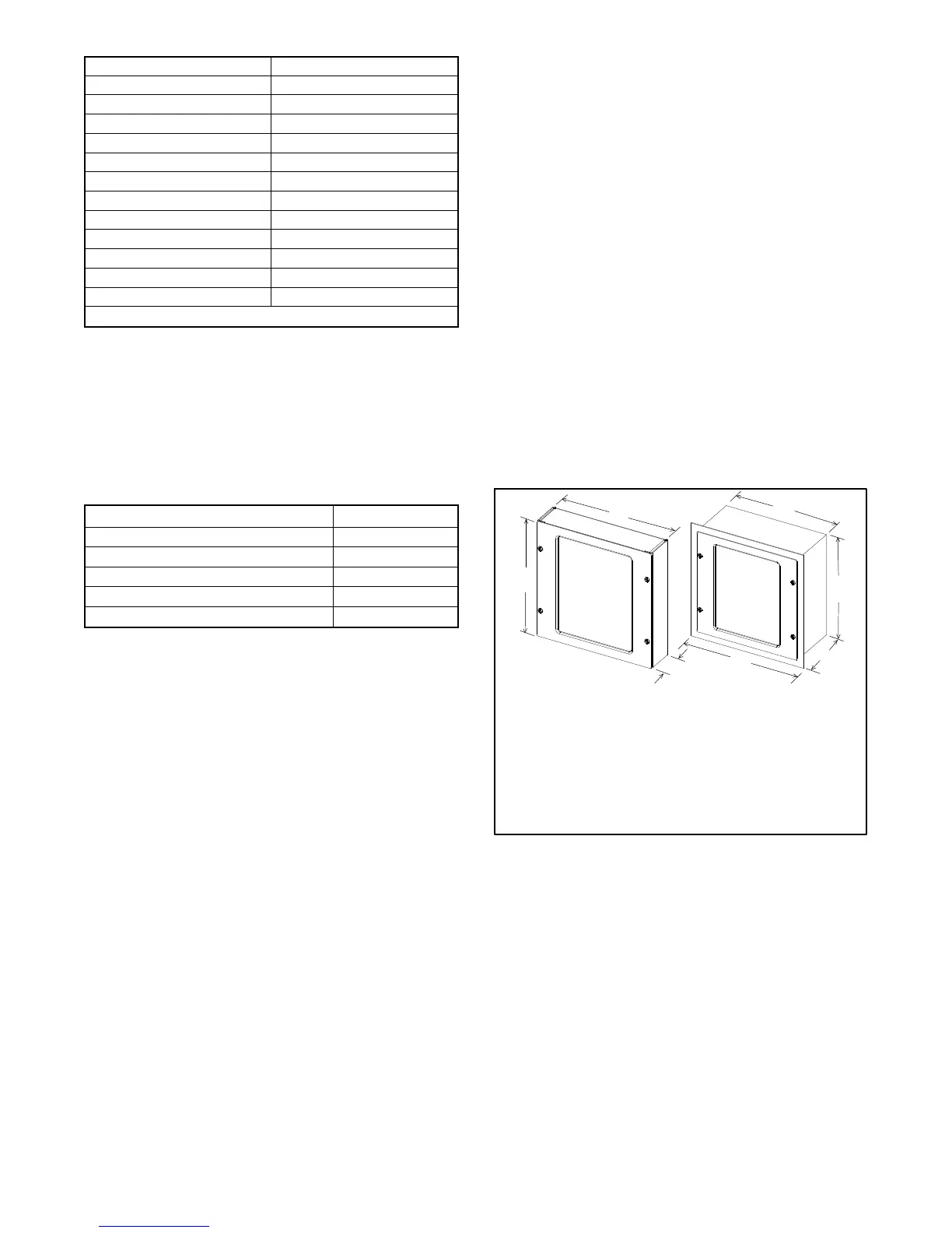
5.1 Select a visible location for mounting the RSA III
up to 853 m (2800 ft.) from the controller. Install
the RSA III, either surface- or flush-mounted, in a
location easily observable by operating
personnel at their work stations. See Figure 14
for RSA III overall dimensions. Refer to
Figure 15 and Figure 16 for the dimension prints.
Note: Locate all RSA III within 853 m (2800 ft.) of
the c ontroller.
Dimensions—W x H x D, mm (in.)
Surface Mounted: 203 x 203 x 76.2 (8.0 x 8.0 x 3.0)
Flush Mounted: 203 x 203 x 76.2 (8.0 x 8.0 x 3.0)
Flush-mounting plate W1: 254 (10.0)
Flush Mounted*: 203 x 203 x 103 (8.0 x 8.0 x 4.1)
Flush-mounting plate W1: 254 (10.0)
* Requires user-supplied Hoffman box 203 x 203 x 102 mm (8 x 8 x 4 in.)
TT-1625-
Surface Mounted Flush Mounted
W
W
W1
D
D
H
H
Figure 14 RSA III Box Dimensions
 Loading...


