TT-1625 7/17 25
6.6 P39, 3-pin isolated/non-isolated jumper.See
Figure 39 for P39 connections. See Figure 20 for
the location of P39 on the RSA III.
Insulated Isolated RS-485 (default setting)
Non-isolated Non-isolated RS-485
Figure 39 P39 Isolation Jumper Connections
When using the DEC 3+ controller, choose the
isolated connection on the master RSA III
where
the RS-485 cable shield and ground leads are
connected at the master RSA III, but are not
grounded to the RSA III circuit board.
Note: When using the DEC 550 and DEC 6000
controllers, choose the
non-isolated
connection on the master RSA III
where
the RS-485 cable shield and ground leads
are connected at the master RSA III and
grounded to the RSA III circuit board. The
non-isolated connection
ties the ground
wire and shield (both of which are
connected to the GND terminal of terminal
block P27) to the same ground as the
RSA III circuit board.
When the slave RSA III is not the only item on
the
network
, use the isolated connection where the
RS-485 cable shield and ground leads are
connected but not grounded to the RSA III circuit
board.
Note: When the slave RSA III is the only item
on
the network
(connects only to a Modbusr
to Ethernet converter), use the
non-isolated connection
where the
RS-485 cable shield and ground leads are
connected and grounded to RSA III circuit
board.
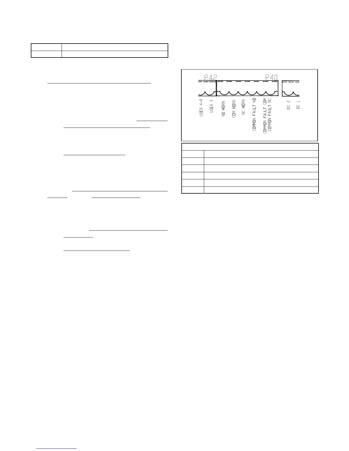
6.7 P40, 6-pin common fault output and horn dry
contacts. These dry contact relays energize
when the alarm horn sounds and activate
user-supplied devices. See Figure 40 for P40
connections. See Figure 20 for the location of
P40 on the RSA III. The dry contacts are rated at
220 VAC @ 0.8 amps and 30 VDC @ 2 amps.
TT-1625
1
6
P40 Output Connections
P40-1 Common fault relay normally closed
P40-2 Common fault relay common
P40-3 Common fault relay normally open
P40-4 Horn relay normally closed
P40-5 Horn relay common
P40-6 Horn relay normally open
Figure 40 P40 Common Fault Output and Alarm
Horn Dry Contacts
 Loading...


