TT-1625 7/17 19
6.3 P27, 6-pin RS-485 connections
(communication between controller and
RSA III master). For RS-485 connections see
Figure 21.
P27 RS-485 Connections (from Controller to Master )
P27-1 (--) Black (from controller)
P27-2 (+) White (from controller)
P27-3 Shield (from controller)
P27-4 (--) Black (to slave or terminating resistor)
P27-5 (+) White (to slave or terminating resistor)
P27-6 Shield (to slave or open)
Note: When using RS-485 communication cable, connect the
“shield” wire at either end but not at both ends.
Figure 21 P27 Connector on Master RSA III
Select and connect the RS-485 wiring from the
controller to the RSA III master using
Belden
#9841 or equivalent
. If there is only one RSA III, it
is the master. If several RSA III are installed,
choose either the RSA III closest to the generator
set or determine which RSA III is more practical
for use as a master and use a daisy chain wiring
configuration for the remaining RSAs. The
RSA III connected to controller MUST be
assigned as the RSA III master.
Connect RS-485 wiring to 6-position Euroblock
plug 294619 (included) and attach to the RSA III
circuit board. The Euroblock connector is
polarized and attaches in one position only. See
Figure 22 for a typical RS-485 connection.
Communication between RSA III Master and
RSA III Slave. Figure 23 shows the master/
slave R S-485 connections and Figure 20 shows
the RSA III with P27 location.
Note: When an RSA III is installed into a system
with existing older RSAs, the RSA III must
be configured as the master.
Note: Controllers, when communicating with the
RSA III, are considered slaves. If the
controller is the last device in the network,
use a terminating resistor on the controller.
See Figure 22. The APM802 and
DEC 8000 controllers have a terminating
resistor located on the controller. See
Figure 36 and Figure 24.
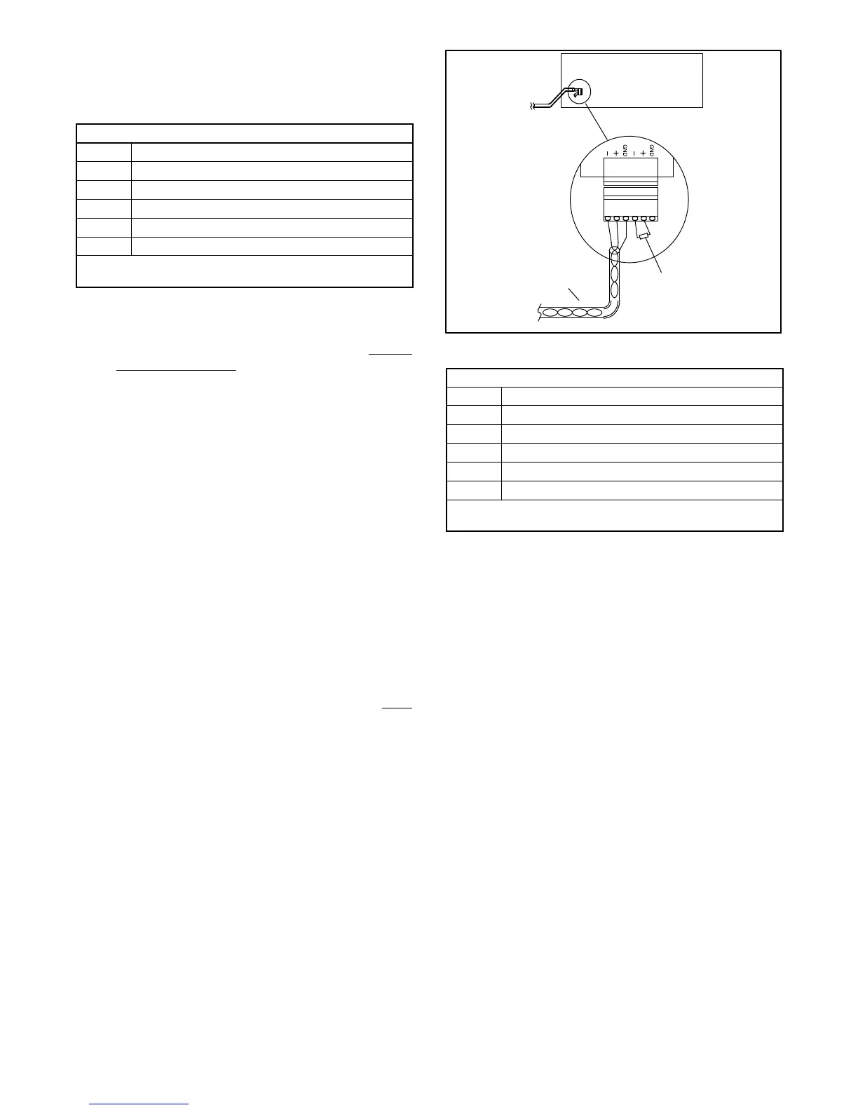
Connect + to +
-- t o --
GND to shield
between devices
Belden #9841
or equivalent
X-6058-27 resistor (121 -ohm)
connect + to -- on last device
in network (resistor is
included with each RSA kit)
Generator Set
Controller
t1283
P20 ( DEC 550)
P21 (DEC 3+)
RSA III
Figure 22 RS-485 Connector Details
P27 RS-485 Connections (from Master to Slave)
P27-1 (--) Black (from master or previous slave)
P27-2 (+) White (from master or previous slave)
P27-3 Shield (from master or previous slave)
P27-4 (--) Black (to next slave or terminating resistor)
P27-5 (+) White (to next slave or terminating resistor)
P27-6 Shield (to next slave or open)
Note: When using RS-485 communication cable, connect the
“shield” wire at either end but not at both ends.
Figure 23 P27 Connection on RSA III Slave
 Loading...


