TP-7070 7/1868 Section 2 Operation
2.12.5 Menus 5 and 6
Except for menu 6.5, communication, menus 5 and 6 are view-only menus that can be seen when logged in as an
operator (1966). The view-only menus are not shown in this document.
2.12.6 Menu 6.5-Communication
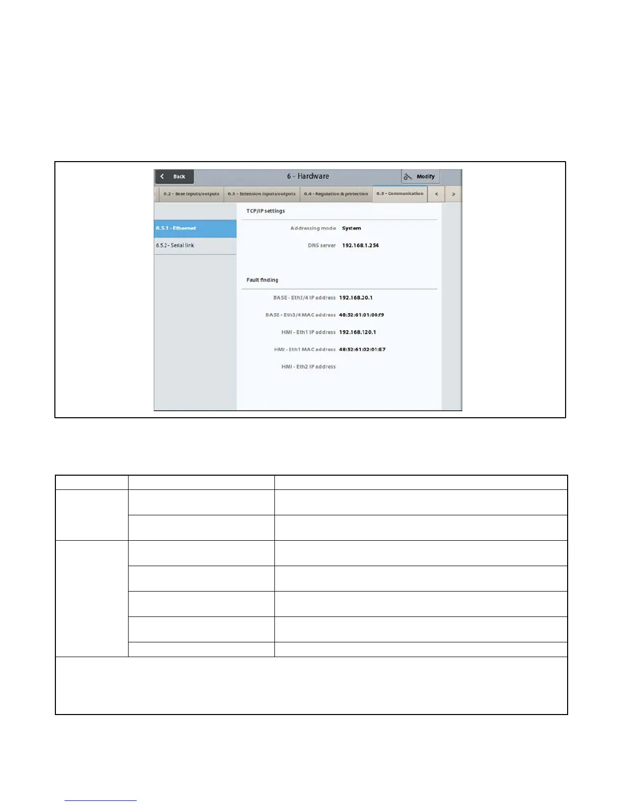
Screen 6.5.1- Ethernet
The 6.5.1-Ethernet screen defines the computer addresses for the Ethernet connections for the base module and the
HMI module.
Figure 2-75 Ethernet Screen
The screen is accessible for modification at the operator level, but only for the TCP/IP configuration section.
Group Title Description and Possible Settings
TCP/IP
Settings
Addressing mode * Choice of address type for the TCP/IP connection: System, Customer
IP, or DHCP.
w
DNS server IP address of the DNS server. The DNS server is used to make the
connection between an APM802 system and an IP address.
Fault Finding Base - Eth3/4 IP address * ] Permanent or temporary identification number for the base module
connected to another base or to a mains.
Base - Eth3/4 MAC address * ] Unique permanent physical identification number, which is stored in
the base module.
HMI - Eth1 IP address * [ Permanent or temporary identification number for the HMI module
connected to another base or to a mains.
HMI - Eth1 MAC address * [ Unique permanent physical identification number, which is stored in
the HMI module.
HMI - Eth2 IP address Not used.
* IP = Internet Protocol; MAC = Media A ccess Control.
[ Eth1 = Ethernet port marked 1 at the rear of the HMI module
] Eth3/4 = Ethernet ports marked 3 or 4 on the front of the base module
w DHCP: the DHCP protocol (Dynamic Host Configuration Protocol) allows an APM system to connect to a network, which dynamically
assigns it an IP address
Figure 2-76 Ethernet Settings
 Loading...

