4
TP-7213 7/21
2.10.6 GFCI Receptacle
To reduce chance of electrical shock:
1. Do not attempt to operate equipment if ground fault circuit interrupter (GFCI) RESET button pops out repeatedly
during use.
2. Remember that only receptacles labeled GFCI have ground fault circuit interrupter protection. Ground Fault Circuit
Interrupter (GFCI) stops power to protected receptacles (A11) if a ground fault (electrical leak) is detected. If RESET
button pops out, equipment plugged into receptacle (A11) may be faulty. If this happens, check equipment carefully. If
equipment appears to be in good condition, press RESET button firmly until a click is heard. This will restore power. If
RESET button pops out again, unplug equipment immediately. Contact a Kohler portable dealer before attempting to
use it again.
Follow below steps to perform GFCI Receptacle Test:
1. Start engine.
2. Press TEST button, if functioning properly RESET button should pop out, stopping power to outlet.
3. If GFCI operation is correct, push RESET button in. If GFCI operates incorrectly, contact a Kohler portable dealer.
Section 3. Getting Started with the Generator Set
3.1 Key to Illustrations
The cover illustrations can be used to identify the various components of the unit. The procedures in the manual refer to these
illustrations using letters and numbers as identifiers: "A1" refers to the number 1 on figure A.
Earth Terminal A1 Exhaust Silencer A14 Circuit Protector A26
Oil Dipstick/Filler Plug A2-B1 Spark Plug A15-E2 Filler Neck B2
Fuel Level Indicator A3
CO Sensor Indicator
Light
A16 Dipstick Upper Limit B3
Fuel Tank Cap A4 Circuit Breaker A17 Dipstick Lower Limit B4
Fuel Valve A5 Change Oil Light A18 Air Filter Cover Screw C1
Air Filter A6
Replace Air Filter
Light
A19 Air Filter Cover C2
Engine On/Off Switch A7
Replace Spark Plug
Light
A20 Foam Element C3
Choke Lever A8
Low Oil Indicator
Light
A21 Air Filter Base C4
Starter Recoil Reel
Handle
A9 Reset A22 Spark Arrester D1
Oil Drain Plug A10-B5 Maintenance Minder A23
Spark Arrester Mounting
Bolt
D2
GFCI Receptacle A11
120/240V/30A
Electrical Socket
A24
Exhaust Silencer
Protection
D3
Fuel Filter A12
120V/30A Electrical
Socket
A25 Spark Plug Cap E1
Power Selector Switch A13
3.2 Initial Commissioning
On taking delivery and commissioning the unit:
1. Check that it is complete and not damaged in any way.
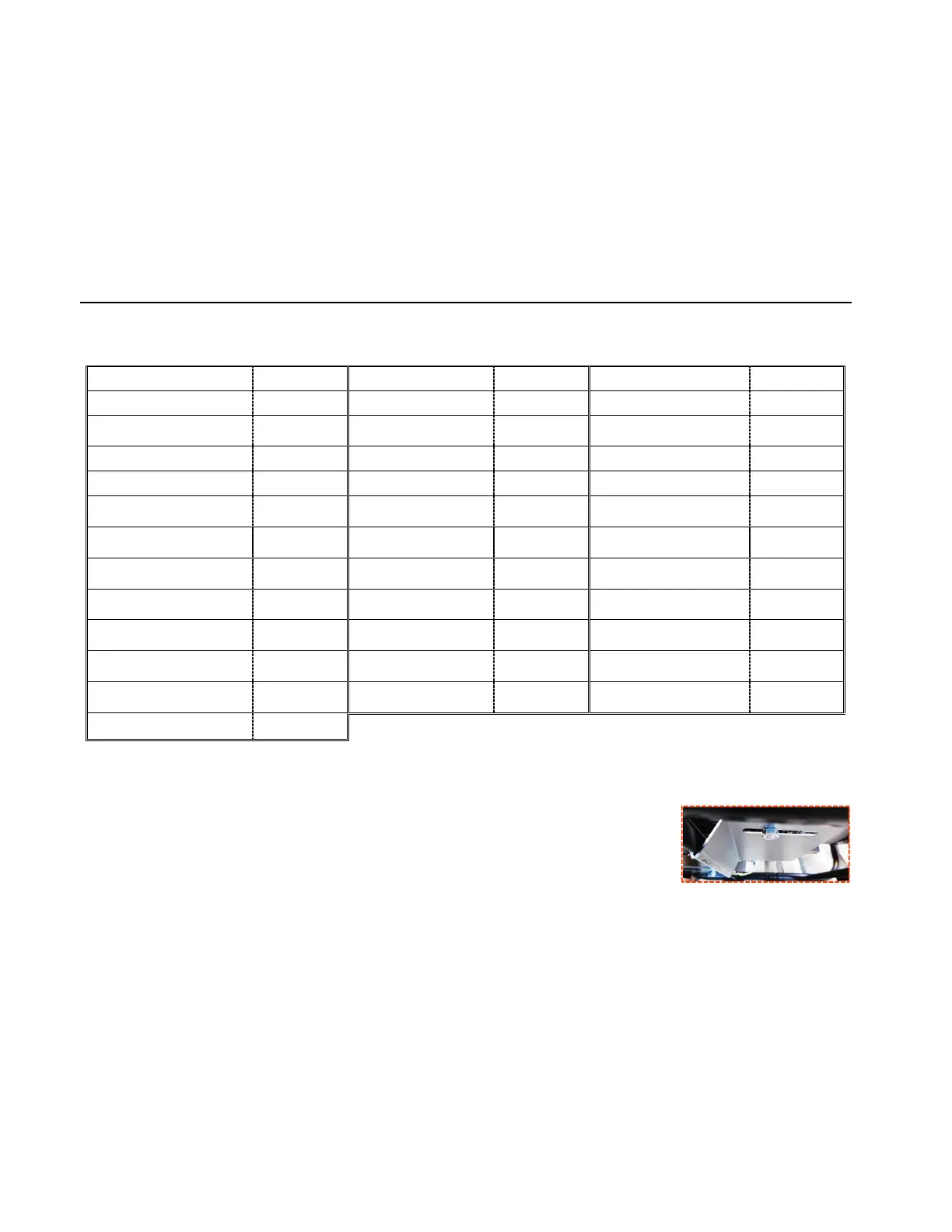
2. If the unit is fitted with a transport bracket, remove it.
The transport bracket is a metal plate located underneath the engine, close to the earth terminal.
Although useful for transportation, it will prevent optimum operation of the unit (noise, vibration).
To remove it: lift the unit slightly and place it on a block then remove the nut (1) and the clamp (2).
3. Check the oil and fuel levels and top them up if necessary.
4. If necessary, connect the battery, starting with the positive terminal.
Observe the polarity of the battery terminals when connecting it: as this could cause serious damage to the electrical equipment.
Some units require a running-in period. Contact your nearest dealer for more information.
Low permeation fuel line must be installed on carbureted Kohler Co. engines to maintain EPA and CARB regulatory compliance.
1
2

 Loading...

