Safety - Section 20 2/13 OM2049
Page 20-18
FAILURE OF DISCHARGE SYSTEM
If the capacitor charge lights remain illuminated, a failure of the normal (fast) capacitor discharge system (RP dis-
charge path) has likely occurred. The slow discharge resistors that are hard wired across the DC link should then
discharge the capacitors. The slow discharge resistors will discharge the DC link to less than 1 VDC in under 7.5
minutes. If after 7.5 minutes, the capacitor charge lights are still illuminated, it must be assumed that the automatic
discharge system is not working and that high voltage is present in the high voltage area.
Measuring Dc Voltage On Capacitors
1. Open the high voltage area doors.
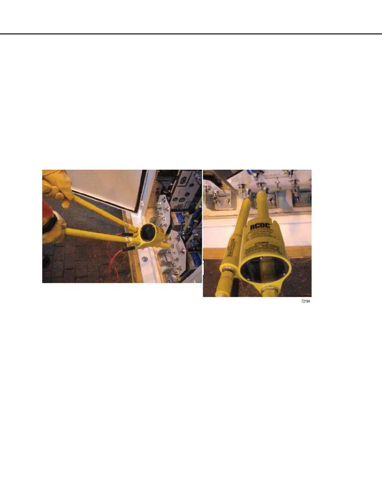
2. With a suitable high voltage meter rated for at least 2000 VDC, such as PC3186 or equivalent, plus suitable
protective equipment, measure the voltage across each of the DC link capacitors. Place one meter lead on
the positive (+) capacitor terminal, and the other meter lead on the negative (-) capacitor terminal, and
observe the voltage. See Figure 20-9 and Figure 20-10. If the voltage is less than 1.0 V the capacitor is suffi-
ciently discharged. Repeat on all DC Link capacitors. If the voltage of any capacitor is above 1.0 V, manually
discharge the capacitor as described in “MANUAL DISCHARGE OF CAPACITORS” on page 19.
FIGURE 20-9. DC METER ON CAPACITOR
 Loading...


