INSTALLATION
H215 AE Rev.: 10 kortho Hot Quick Coder-D
5-3
1. Preheatunit
2. HeatingringandHotroll
3. Textholderintextholderslot
4. Removablehandle
5.4 Mounting the control box
Findasecurelocation,whichiseasilyaccessibleforoperators,tomountthecontrolbox.Referto Appendix
B,‘ControlboxHQC‐D’forthedimensionsofthemountingholes.
Fixitonapositionnearthecodingunitbracketandguidethecablessothatthecodingunitcanrotate
and
movebackandforthwithinthedimensionsofthebracket.ConnectthecodingunitcabletotheX2connector
ofthecontrolboxandusetheconnectorlocktolockit.
Usetheelectricaldiagram, AppendixD‘Electricaldiagram,ControlboxI/O’,todeterminewhichinterface
optionsuitsbest
withthehostmachine.Openthecontrolboxtogainaccesstotheterminalblocks.Putan
interfacecablethroughoneofthecableglandsandconnectthewirestotheproperinputoroutput.Incase
ofasensordriventriggerusetheothercableglandforthesensorcable.
5.5 Initial setup
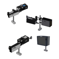
5.5.1 Prepare the text holder
Thetext holderhasaprintingareaof10x20mmor10x24mm.Theprintingareahasaspecially shapedprofile.
Thetext charactersandclichéshavethesameprofileonthereverse.Th etextch aracte rsandclichésareappliedto
thetextholderwitha
simpleprintingmovement.
Fig. 5.5 Textholderandremovablehandle.
Theʹblankspaceʹin thetext c haract ersonthesam eʺlineʺshouldbecompletelyfilledwithspacech aracte rs.Thisin
ordertofixthetextposition.
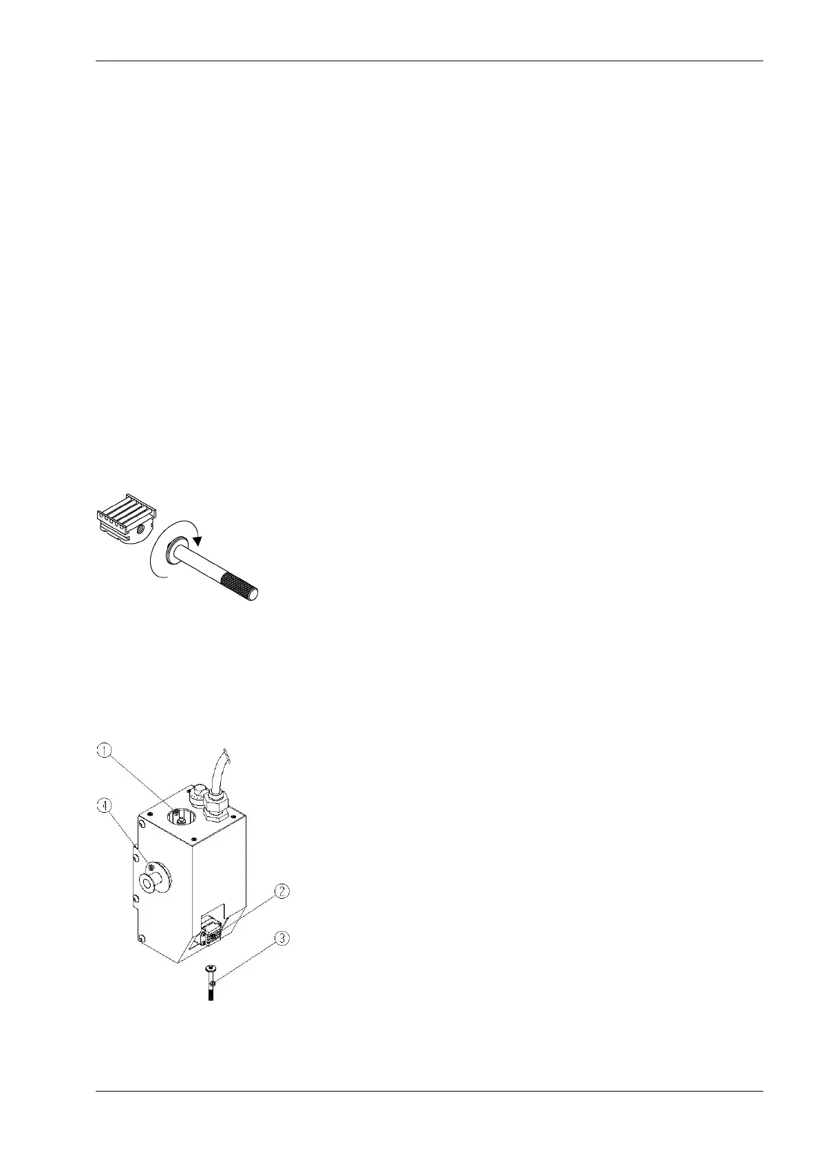
5.5.2 Placing a text holder
Fig. 5.6 Codingunit.
1. Checkbyvisualinspectionfordamageoftheprinter.
 Loading...