650T/650R - Your 650T/650R DVI/Coax Transmitter/Receiver
4 Your 650T/650R DVI/Coax
Transmitter/Receiver
This section defines the 650T DVI-Coax Transmitter (see Section 4.1) and the
650R Coax-DVI Receiver (see Section 4.2)
4.1 Your 650T DVI-Coax Transmitter
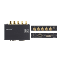
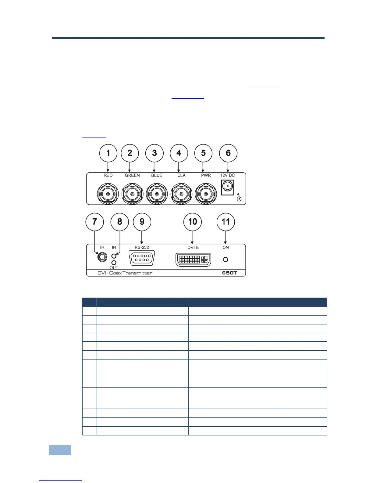
Figure 1 defines the 650T:
Figure 1: 650T/650R HDMI/Coax Transmitter/Receiver
Transmits the red signal to the 650R
GREEN Output BNC Connector
Transmits the green signal to the 650R
BLUE Output BNC Connector
Transmits the blue signal to the 650R
Transmits the clock signal to the 650R
Transmits power and the IR signal to the 650R
+12V DC connector for powering the unit
Connects to an IR sensor or transmitter
Compatible with a Kramer transmitter and via a Kramer
external remote IR receiver: C-A35M/IRR or C-A35M/IRE or
C-A35M/2IRE
The IN LED Illuminates when an input source is
connected. The OUT LED illuminates when an output
acceptor is connected
RS-232 9-pin D-sub Connector
Connects to an RS-232 computer source
Illuminates when receiving power
 Loading...