6-9
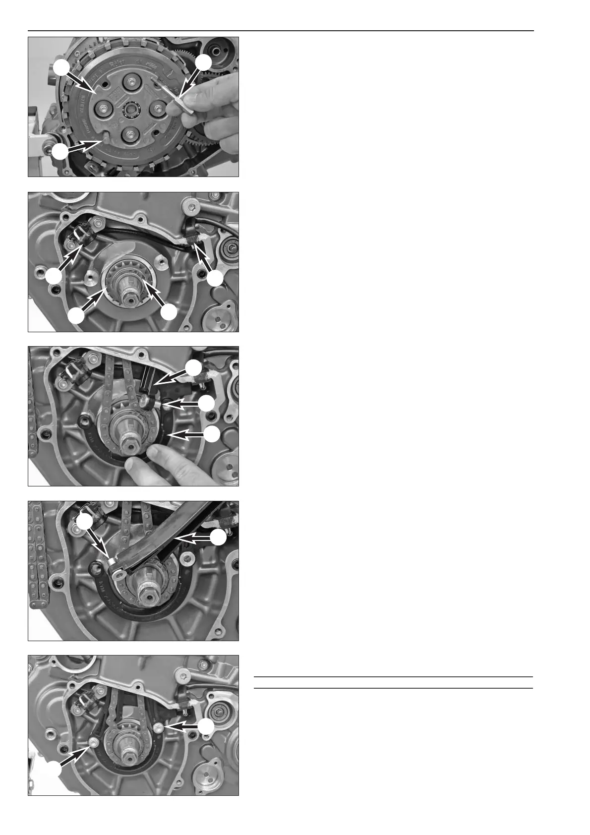
– Mounting the pressure cap 1.
– Mount the clutch screws with washers and springs and tighten in
stages in a crosswise direction to 6 Nm.
– Remove special tool 750.29.033.000
2.
Mounting the timing chain pinion and timing chain
– Mount the shaft key.
– Heat the timing chain pinion
3 to approx. 150° C and slide onto
the crankshaft with the larger chamfer first.
– Mount the lock ring
4.
– Mount the pulse generator
5, lock the screws (M6x15) with Loctite
243 and tighten to 10 Nm.
– Apply Loctite 5910 (584.29.059.200) to the cable guide
6 and
press into the opening.
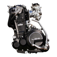
– Thread the timing chain and position it on the timing chain pinion.
NOTE: pay attention to the direction of travel if mounting a used timing
chain.
– Position and hold the clip
7.
NOTE: place the cable for the pulse generator in the clip's cable duct.
– Lower the tensioning rail
8 into the chain tunnel, tilt slightly as
shown in the photo and insert the sleeve
9 in the clip.
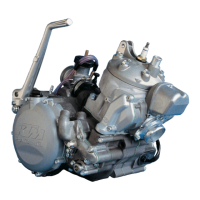
– Lower the guide rail
bk into the chain tunnel and insert the sleeve bl
in the clip.
– Apply Loctite 243 to the screws
bm (M6x30) for the timing chain
guide and tighten to 10 Nm.
!
CAUTION
!
M
AKE SURE NO LOCTITE 243 DRIPS BETWEEN THE TIMING CHAIN GUIDES AND
THE SLEEVES SINCE IT WILL CAUSE THE TIMING CHAIN GUIDES TO LOCK AND
BREAK
.
– Make sure both rails operate smoothly.
5
1
2
2
6
7
8
9
bk
bl
3
4
bm
bm