3. CAB INSTALLATION
TOOLS REQUIRED:
• Two (2) 3/4” and one (1) 1/2” SAE wrenches or sockets
• Two (2) 14mm and one (1) 12mm Metric wrenches or sockets
QTY: HARDWARE
6 5/16-18 x 1” Flanged Head Bolts
2 1/2-13 x 1” Flanged Head Bolts
2 1/2-13 Flanged Nylon-Insert Nut
WARNING: Use only appropriately rated equipment to lift the cab.
NOTE: Total weight of the cab assembly without doors or accessories
is approximately 230 lbs. Weight of the cab with doors, not
including accessories, is approximately 340 lbs.
3.1 Replace the large thumb screws from the front of the ROPS
with two M10 bolts from the hardware kit.
3.2 Fold the tractor ROPS down by removing the pin, lower it and
secure it via the pin in the lowered position. Move the seat into
its forward position.
3.3 Remove the doors from the cab (see section 4.3) to the reduce
weight on the frame as the cab is lifted. The rear window can
also be removed to further reduce the weight.
3.4 Remove the bolts securing the cab to the shipping pallet:
2 (two) bolts in each floorboard and 1 (one) bolt and nut in each
rear mount.
NOTE: The pallet may be retained for seasonal storage of the cab.
3.5 Lift the cab off the pallet via the lifting rings in the roof. The cab
will tip slightly forward as it’s lifted via the rings.
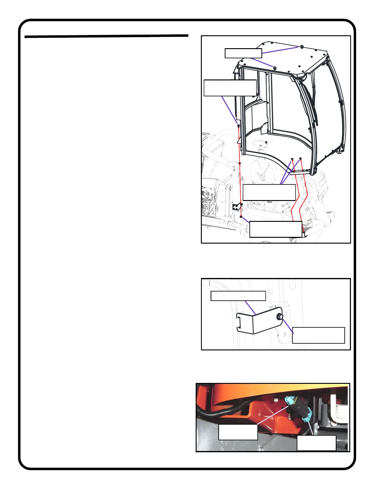
3.6 Carefully lower the cab over the tractor oriented per figure 3.5
until the floorboards are about 1/4 inch to 1/2 inch above the
front mounts. Make sure the cab wire at the front right corner is
free and not pinched underneath the floorboard.
3.7 Align the forward holes in the floorboard with the holes in the
front mounts and install a 5/16” bolt through the 2 (two) holes in
each floorboard and into the threaded inserts in the front
mounts. Insert the bolts only far enough to catch the
threads at this time. Use caution to avoid cross-threading
factory installed threaded inserts.
3.8 Lower the cab until the rear mounts on the cab are close to the
rear mounts on the side of the vehicle ROPS. Place a 1/2” bolt
through each cab rear mount and install a nut underneath.
3.9 Make sure the rubber flap at the rear left of the cab folds neatly
around the handle on the tractor and has no visible gaps
against the rear panel and fender.
3.10 Raise and secure the ROPS into its upright position and over
the upper ROPS mounts on the vehicle.
3.11 Check the fit of the cab, adjust as needed and secure the Upper
Mount Clamp from the hardware box onto each upper ROPS
mount with a 5/16” bolt (see fig. 3.11).
3.12 Tighten both 5/16” bolts in each floorboard, and the 1/2” bolts
and nuts in each lower rear mount, and tighten the M10 bolts for
the lower rear mounts.
Tighten all bolts to the following specifications:
1/2-13 - 80 - 96 ft-lbs (108 - 130 N-M)
5/16-18 - 17 - 20.5 ft-lbs (23.1 - 27.8)
M10 - 35.5 - 41.2 ft-lbs (48.1 - 55.8 N-M)
3.13 Attach the weather-pack connector at the front, right of the cab
to the connector from the relay harness, under the right front
mount (see fig. 3.13).
NOTE: The lifting rings may be removed and replaced with bolts if
desired. Two 5/16-18 x 1” bolts and replacement nylon
washers are included in the hardware kit for this purpose.
5/16-18 x 1”
QTY: two (2) per side
1/2-13 Nut
QTY: one (1) per side
1/2-13 x 1”
QTY: one (1) per side
Lifting Rings
Fig. 3.5: Cab onto Tractor orientation
Male plug
from Cab
Female plug
from Tractor
Fig. 3.13: Cab to Tractor plug connection
5/16-18 x 1”
QTY: one (1) per side
Upper Mount Clamp
Fig. 3.11: Upper ROPS Clamps
P. 7 of 14
 Loading...