SHOP MANUAL
Paragraphs 90-91
Inspect all parts for wear, scoring or
other damage and renew as necessary.
Be sure to renew all "0" rings.
Reassemble valve by reversing
disassembly procedure. Reinstall valve
assembly using new "0" rings and
tighten mounting bolts to a torque of
24-27 N;m (18-20 ft.-lbs.). Check and ad-
just relief valve pressure as outlined in
paragraph 88.
SHUTTLE CLUTCHES
Model L355
90.
R&R OVERHAUL. To remove
shuttle transmission, tractor must first
be split between engine and clutch hous-
ing as outlined in paragraph 64. Remove
steering wheel, instrument panel, fuel
tank and support assembly and steering
gear assembly. Remove hydraulic pipe
from shuttle valve and disconnect clutch
rod from clutch release lever. Support
transmission housing and clutch housing
separately, then remove clutch housing
mounting bolts. Separate clutch housing
from transmission housing.
To disassemble shuttle transmission,
remove set screw (7-Fig. 122) and
mounting cap screws from gearcase (6).
Use two jackscrews to lift gearcase from
clutch housing. Remove reverse idler
shaft (5), gear (4) and bearings from
gearcase. Remove shuttle control valve
and valve spacer block. Remove moun-
ting cap screws from hydraulic manifold
(1-Fig. 123), then use two jackscrews
to lift manifold off clutch housing. Screw
two cap screws into upper and lower
shaft seal retainers (2-Fig. 124), then
pull retainers out of housing. Remove
seal rings (4) and snap ring
(5),
then tap
shafts rearward to remove clutch
assemblies. Remove cap screws from
mainshaft bearing case (4-Fig. 123),
then withdraw mainshaft assembly from
clutch housing. Remove snap ring (11)
and gear (9), then tap mainshaft out of
bearing case.
Disassembly procedure is the same for
either clutch pack. Remove retaining
ring (9-Fig. 124), gear (10) and inner
race (11), then separate clutch shaft
assembly from clutch pack. Remove
snap ring (31), then tap clutch shaft (23
or 24) out of bearings and gear (27 or
28).
Remove snap ring (21) and remove
back-up plate (20), clutch discs (19) and
steel plates (18) from clutch case (12).
Use special clutch tool (1-Fig. 125) ,
Code No. 07916-52071, or a similar
horseshoe shaped tool and a press to
compress piston return spring (15-Fig.
124).
Remove snap ring
(17),
then slowly
release spring tension and remove
spring seat (16), spring (15) and piston
(14) from clutch case.
Inspect all parts for excessive wear or
other damage. Renew clutch discs and
plates if worn, burned or warped.
Renew all "0" rings, seal rings and oil
seals.
To reassemble clutch pack, reverse
the disassembly procedure. Be sure
thrust washers are installed with their
oil groove toward gears. Lubricate seals
and "0" rings with clean oil prior to
reassembly. Tighten hydraulic manifold
mounting cap screws to a torque of
24-27 N-m (18-20 ft.-lbs.). Be sure "0"
rings are in place when reinstalling shut-
tle valve and valve mounting spacer.
Tighten spacer and valve mounting cap
screws to a torque of 24-27 N-m (18-20
ft.-lbs.).
DIFFERENTIAL
AND BEVEL GEARS
All Models
91.
REMOVE AND REINSTALL.
To remove differential and main drive
bevel ring gear,
-
first drain oil from
transmission and final drive housings.
Wedge front axle to prevent tractor
from tipping, securely block front and
rear transmission housing and remove
rear wheels, fenders and seat. Remove
differential lock pedal. Support final
drive housing with a suitable hoist,
remove mounting cap screws and detach
both final drives from transmission
housing. Disconnect brake linkage from
brake cam lever. Remove brake
assemblies and differential gear shafts
from transmission housing. Disconnect
hydraulic pipes from rockshaft housing,
remove mounting cap screws and lift
housing
ofT
tranmission housing. Remove
differentia] lock cam lever and shift fork.
Support differential assembly, then use
two jackscrews to lift bearing cases off
housing. Lift differential assembly out of
rear housing. Be sure to identify shims
and bearing cases so they can be reinstall-
ed in their original positions. Bearing
cases are not interchangeable.
If main drive bevel pinion shaft re-
quires renewal, rear transmission hous-
ing must be separated from front hous-
ing. Remove bevel pinion shaft as outlin-
ed in TRANSMISSION section.
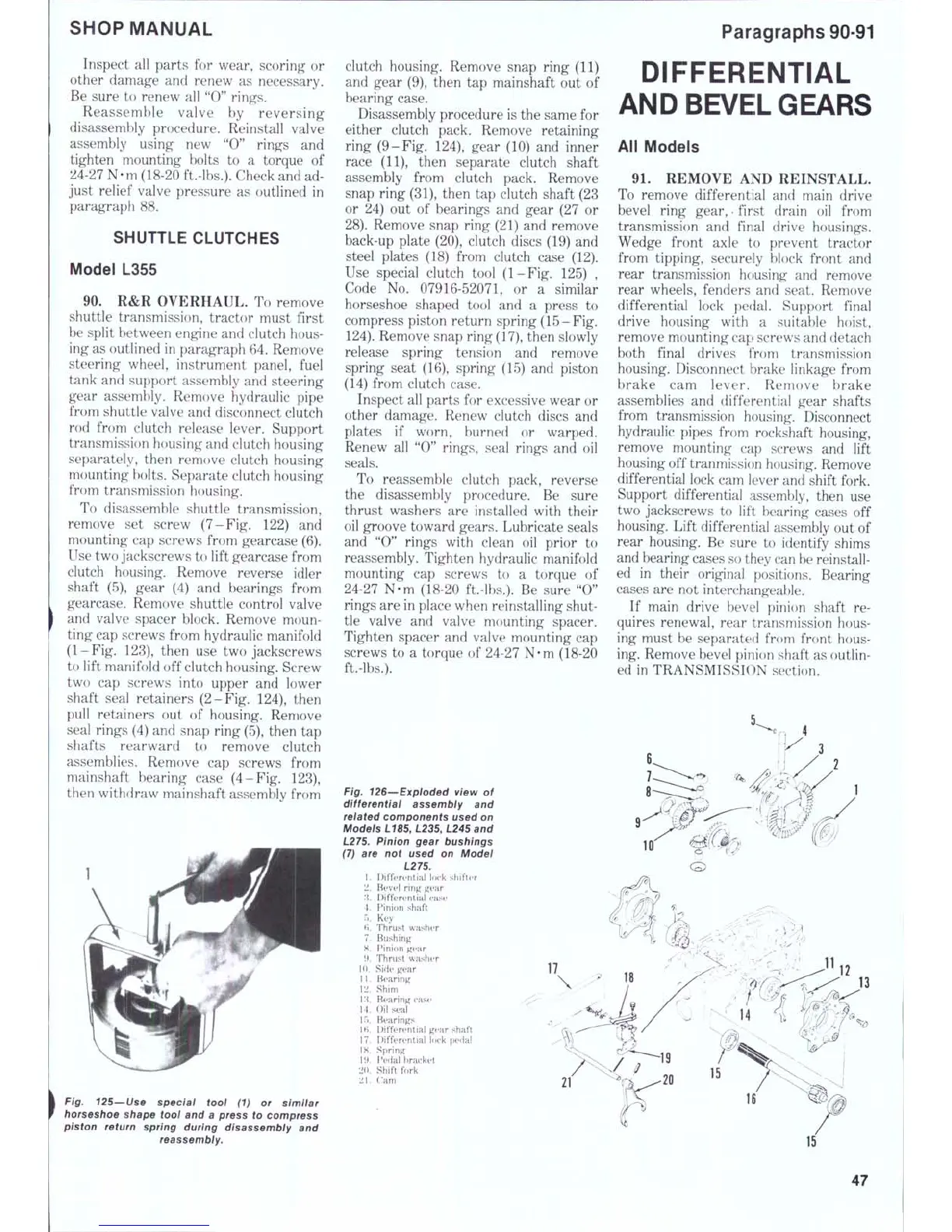
Fig. 126—Exploded view of
differential assembly and
related components used on
Models L185, L235, L245 and
L275. Pinion gear bushings
(7) are not used on Modei
L275.
1.
Differential lock shifter
2.
Bt'Vt'I ring gear
.'{.
Differential case
4.
Pinion shaft
r.. Key
f;. Thrust washer
7.
Bushing
8. Pinion gear
i>.
Thrust washer
10.
Side gear
11.
Bearing
12.
Shim
I'i. Bearing case
14.
Oil seal
15.
Bearings
16.
Differential gear shaft
17.
Differential lock pedal
18.
Spring
19.
Pedal bracket
20.
Shift fork
21.
Cam
Fig. 125—Use speciai tool (1) or simiiar
horseshoe shape tool and a press to compress
piston return spring during disassembly and
reassembly.
21
47
 Loading...


